Auxiliary nozzle for air-jet loom and air-jet loom

A technology for auxiliary nozzles and air-jet looms, which is applied in looms, textiles, textiles, and papermaking, etc. It can solve the problems of poor injection ability of auxiliary nozzles, achieve strong injection capabilities, maintain stability, and reduce air consumption.

Active Publication Date: 2017-08-01
ZHEJIANG SCI-TECH UNIV
View PDF9 Cites 0 Cited by
  • Summary
  • Abstract
  • Description
  • Claims
  • Application Information

AI Technical Summary

Problems solved by technology

[0007] The invention provides an auxiliary nozzle for an air-jet loom, which solves the problem of poor spraying ability of the auxiliary nozzle in the prior art

Method used


Image

  • Auxiliary nozzle for air-jet loom and air-jet loom
  • Auxiliary nozzle for air-jet loom and air-jet loom
  • Auxiliary nozzle for air-jet loom and air-jet loom

Examples


Embodiment 1

[0056] Example 1 Auxiliary nozzle for air jet loom

[0057] Such as figure 1 As shown, an auxiliary nozzle for an air jet loom in this embodiment includes a nozzle seat 1 and a nozzle 2 penetrating and installed in the center hole of the nozzle seat 1. The jet end of the nozzle 2 is provided with a first jet 3 and a second jet 4 arranged in parallel. Both the first jet 3 and the second jet 4 are provided with a jet hole 5, and the orientation of the two jet holes 5 is the same.

[0058] by figure 2 It can be seen that the air jet holes 5 in this embodiment are all rectangular.

[0059] Such as image 3 As shown, the nozzle 2 is provided with an airflow chamber 6, the first nozzle 3 is provided with a first airflow channel 7 communicating with the airflow chamber 6, and the second nozzle 4 is provided with a second airflow channel communicating with the airflow chamber 6. The air flow channel 8, the first air flow channel 7 and the second air flow channel 8 are arranged side by sid...

Embodiment 2

[0082] Example 2 An air jet loom

[0083] Such as Picture 11 As shown, an air-jet loom of this embodiment includes a special-shaped reed 17 provided with a weft passage 16, a main nozzle 18 facing the starting end of the weft passage 16, and the auxiliary in embodiment 1 arranged in sequence along the extending direction of the weft passage 16. nozzle.

[0084] In this embodiment, the auxiliary nozzles include a front auxiliary nozzle group 19 and a rear auxiliary nozzle 20 arranged in sequence along the extending direction of the weft passage 16, and each auxiliary nozzle is controlled by an independent solenoid valve.

[0085] The front auxiliary nozzle group 19 includes a plurality of first auxiliary nozzles 21, and the rear auxiliary nozzle group 20 includes four second auxiliary nozzles 22.

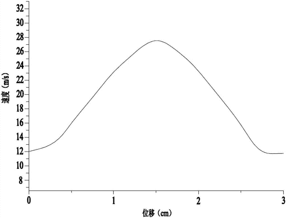
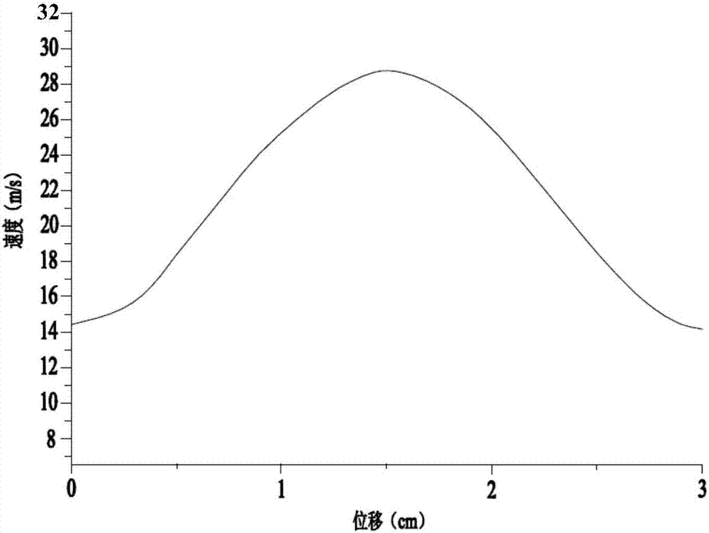
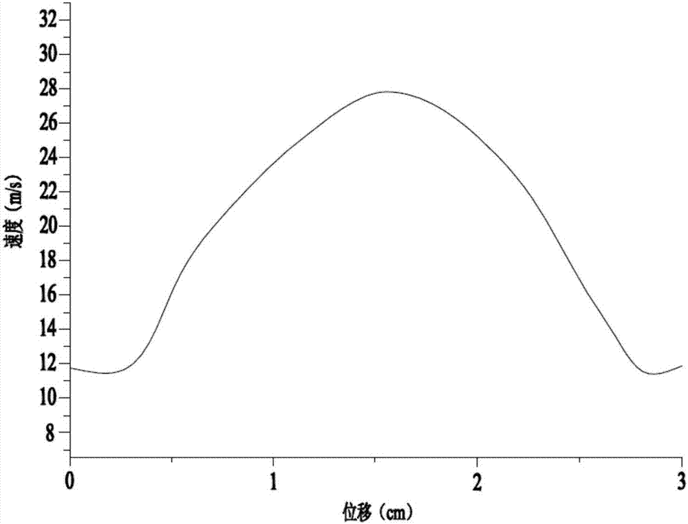
[0086] Since the reasonable arrangement of the auxiliary nozzles can effectively reduce the air consumption in the special-shaped reed, this embodiment discusses and analyzes the arrangemen...


PUM


Abstract

The invention discloses an auxiliary nozzle for an air-jet loom. The auxiliary nozzle for the air-jet loom comprises a nozzle body with an air flow chamber and a sprayer which is arranged on the nozzle body, wherein the sprayer comprises a first sprayer and a second sprayer which are arranged in parallel, a first air flow channel which is communicated with the air flow chamber is arranged in the first sprayer, a second air flow channel which is communicated with the air flow chamber is arranged in the second sprayer, rectangular blowholes are arranged on the first and the second sprayers, and the directions of the blowholes which are arranged on the first and the second sprayers are consistent. The auxiliary nozzle for the air-jet loom has strong injection capacity, specific performance in that the auxiliary nozzle for the air-jet loom is excellent in air flow stability on a flow channel section which is 250mm away from the blowholes, and can achieve 32m / s maximum speed of gas flow rate. Simultaneously, the first and the second sprayers respectively spray air from the upper and the lower sides of weft yarns, and enable the two sides of the weft yarns to evenly bear force, thereby being capable of perfectly maintaining kinematic velocity of the weft yarns, reducing fluctuation of the weft yarns, and guaranteeing stability of the weft yarns.

Description

Technical field [0001] The invention relates to a textile equipment, in particular to an auxiliary nozzle for an air jet loom and an air jet loom. Background technique [0002] Existing air jet looms generally include a special-shaped reed provided with a weft passage, a main nozzle facing the starting end of the weft passage, and auxiliary nozzles arranged in sequence along the extending direction of the weft passage. [0003] In the air jet loom, weft insertion is mainly realized by the air jet injected from the main nozzle into the weft guide channel arranged in the shed of the warp yarn and the air jet injected by the auxiliary nozzle to assist the weft yarn through the shed. The auxiliary nozzle for air-jet spinning sprays before the weft yarn arrives, drives the air movement in front of the weft yarn, reduces the air resistance to the weft yarn, makes the front end of the weft yarn generate a relatively negative pressure, and attracts the weft yarn, so as to supplement the ma...

Claims


Application Information

Patent Timeline
Patent Type & Authority Patents(China)
IPC IPC(8): D03D47/30
CPCD03D47/30D03D47/302D03D47/304
Inventor 金玉珍胡小冬胡旭东
Owner ZHEJIANG SCI-TECH UNIV
Why Eureka
Try Eureka