Self-piercing adhesive riveting connection device and adhesive riveting method

A riveted connection and self-piercing technology, applied in furnaces, furnace types, heat treatment equipment, etc., can solve the problems of difficult deformation of ultra-high-strength steels, inability to form effective joints, etc., to increase the joint connection strength and reduce the thermal convection between plates. and heat radiation, the effect of reducing requirements

Inactive Publication Date: 2017-07-04
JILIN UNIV
View PDF7 Cites 0 Cited by
  • Summary
  • Abstract
  • Description
  • Claims
  • Application Information

AI Technical Summary

Problems solved by technology

[0006] The purpose of this invention is to design and develop a self-piercing sticky riveting connection device based on the semi-hollow self-piercing riveting connection technology. By introducing the tempering and annealing characteristics of metal materials, local tempering heat treatment is performed on ultra-high-strength steel, and the riveting is properly reduced. The strength of the ultra-high-strength steel near the riveting point greatly improves the ductility of the ultra-high-strength steel near the riveting point, and solves the problem that the ultra-high-strength steel is difficult to deform and cannot form an effective joint

Method used


Image

  • Self-piercing adhesive riveting connection device and adhesive riveting method
  • Self-piercing adhesive riveting connection device and adhesive riveting method
  • Self-piercing adhesive riveting connection device and adhesive riveting method

Examples


Embodiment Construction

[0047] The present invention will be further described in detail below in conjunction with the accompanying drawings, so that those skilled in the art can implement it with reference to the description.

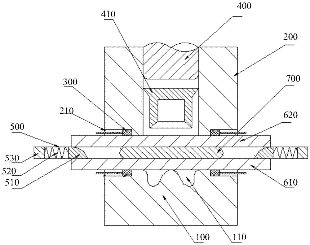
[0048] Such as figure 1 As shown, the self-piercing adhesive riveting connection device provided by the present invention includes: a composite die 100 , a composite blank holder 200 , a thermally conductive electrode 300 and a punch 400 .

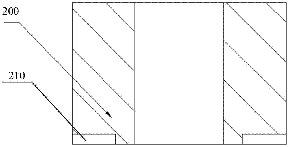
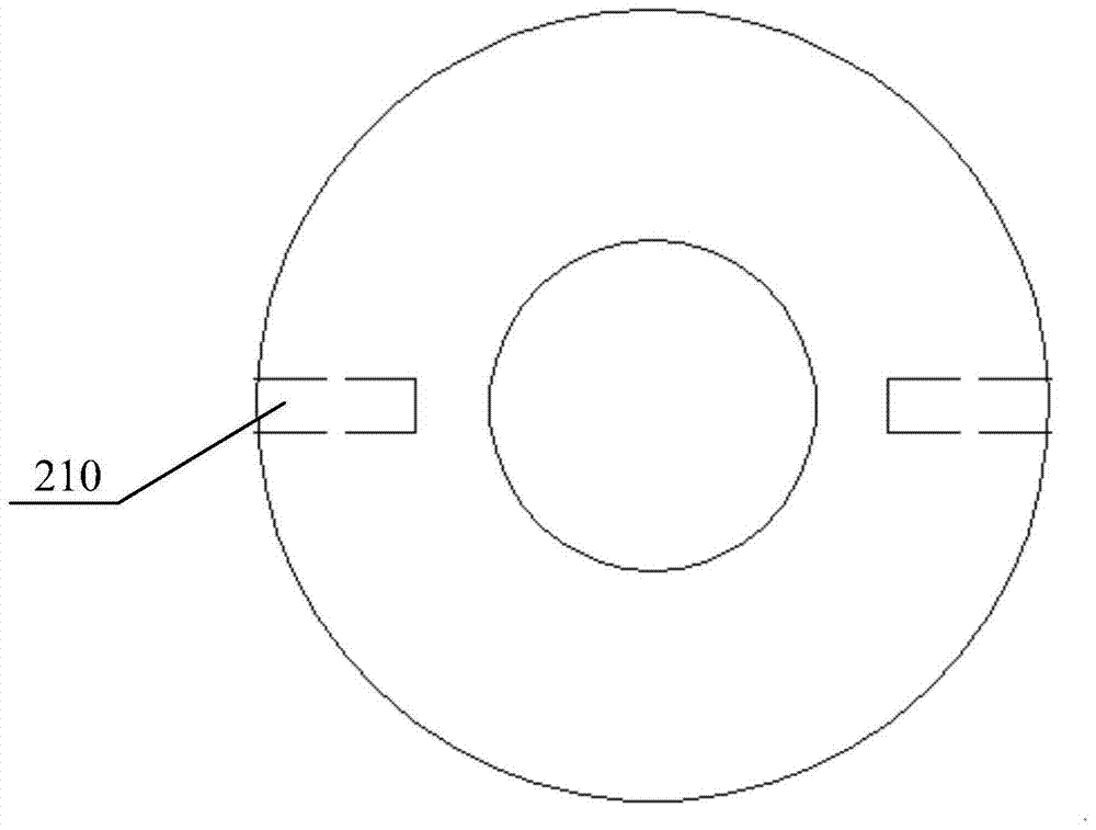
[0049] Such as Figure 2-3 As shown, the composite binder ring 200 is set opposite to the composite die 100, and the center of the composite binder ring 200 is provided with a through hole, and the bottom surface of the composite binder ring 200 is connected to the top surface of the composite die 100 in a contactable manner. On the bottom ring surface of the edge ring 200, a plurality of rectangular grooves 210 with the same structure are provided from the outside to the inside. The through hole at the center of the binder ring 200 is ...


PUM

PropertyMeasurementUnit
diameteraaaaaaaaaa
lengthaaaaaaaaaa

Abstract

A self-piercing adhesive riveting connection device, comprising: a composite die, on which an annular groove is arranged; a composite blank holder, which is vertically opposite to the composite die, and the composite blank holder can move in the vertical direction , used to press the parts to be riveted; the number of heat-conducting electrodes is multiple, which are respectively arranged at the bottom of the composite blank holder and the upper part of the composite die; the heat-conducting electrodes can independently heat different parts to be riveted; punches, which are solid The ring-shaped structural part is arranged inside the center hole of the composite blank holder and can slide up and down axially along the center hole; the ductility of the ultra-high-strength steel near the riveting point is greatly improved, and the difficulty of deformation of the ultra-high-strength steel is solved. The problem that effective joints cannot be formed and a self-piercing adhesive riveting connection method is provided. By precisely controlling the punching speed of the punch, the requirements for the strength of the rivet, the punching ability of the equipment, and the rigidity of the C-frame of the riveting gun are reduced, and the production is reduced. cost.

Description

technical field [0001] The invention relates to the technical field of high-strength steel riveting, in particular to a self-piercing adhesive riveting connection device and a method for realizing punching adhesive riveting. Background technique [0002] The development of the automobile industry has brought enormous pressure on energy, climate, and the environment. Reducing fuel consumption, energy conservation and emission reduction has become an urgent problem for Chinese automobiles, and automobile lightweight has become an important means to solve this problem. [0003] Lightweight materials such as high-strength steel plates, aluminum alloys, and magnesium alloys have replaced traditional steel plates and become the main method for achieving lightweight automobiles, while the application of new materials poses a huge challenge to automotive connection technology. When traditional resistance spot welding is used to connect high-strength steel and aluminum alloy, due to ...

Claims


Application Information

Patent Timeline
Patent Type & Authority Patents(China)
IPC IPC(8): B21J15/04B21J15/38C21D1/34C21D9/00
CPCC21D1/34C21D9/0068B21J15/04B21J15/38C21D2221/00B21J15/025B21J15/08B21J15/36
Inventor 庄蔚敏张凯希胡哲李冰娇解东旋敖文宏徐纪栓杨冠男刘西洋
Owner JILIN UNIV
Why Eureka
Try Eureka