
Self-piercing riveting device of ultrahigh strength steel plates or/and aluminum alloy plates

An aluminum alloy plate, self-piercing riveting technology, applied in the field of processing equipment, to achieve the effect of avoiding cracks

Inactive Publication Date: 2014-02-26
JILIN UNIV
View PDF8 Cites 46 Cited by
  • Summary
  • Abstract
  • Description
  • Claims
  • Application Information

AI Technical Summary

Problems solved by technology

[0009] The technical problem to be solved by the present invention is to overcome the problem that the existing technology cannot realize the connection between ultra-high-strength steels and the connection between ultra-high-strength steels and aluminum alloys under the premise of ensuring that the mechanical properties of ultra-high-strength steel plates are not affected, and provides a Self-piercing riveting device between two kinds of ultra-high-strength steel plates or between ultra-high-strength steel plates and aluminum alloy plates

Method used


Image

  • Self-piercing riveting device of ultrahigh strength steel plates or/and aluminum alloy plates
  • Self-piercing riveting device of ultrahigh strength steel plates or/and aluminum alloy plates
  • Self-piercing riveting device of ultrahigh strength steel plates or/and aluminum alloy plates

Examples


Embodiment

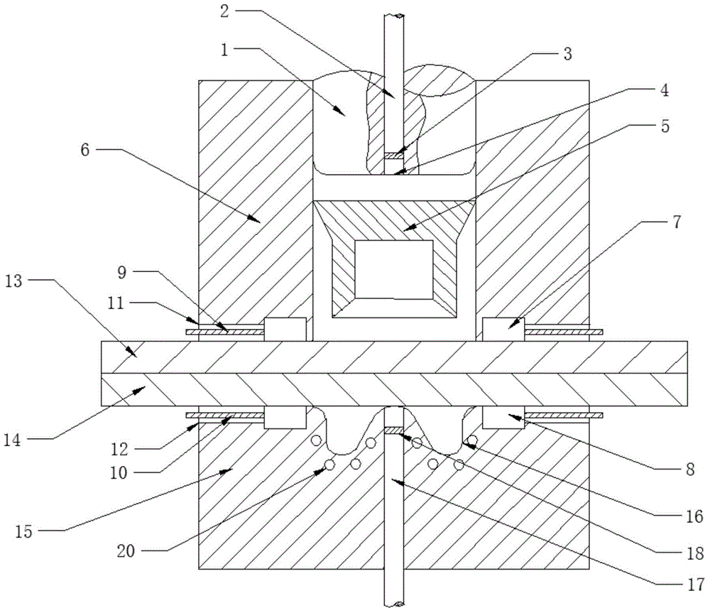
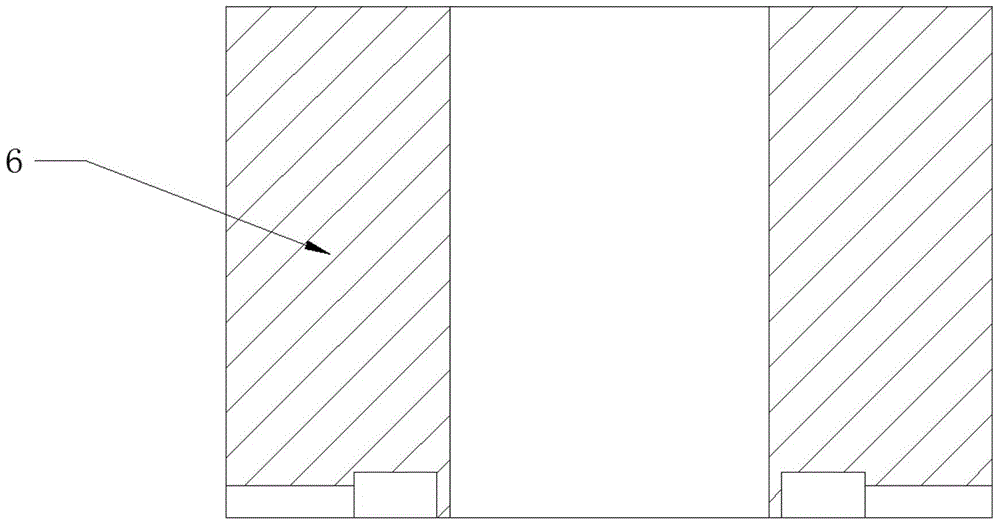
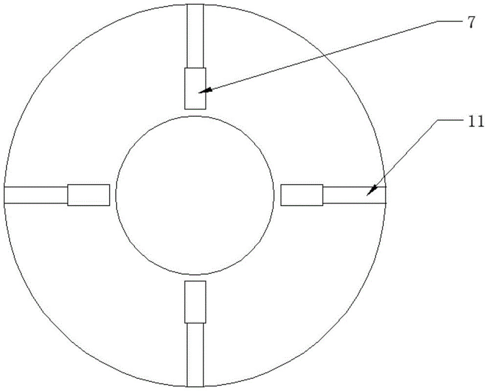
[0052] refer to figure 1 The self-piercing riveting device between ultra-high-strength steel plates or aluminum alloy plates according to the present invention includes a composite punch 1 (including a first optical fiber tube 2 and a first concave lens 3), a composite blank holder 6 (including 2 to 4 Thermistor with the same structure), composite concave mold 15 (second optical fiber tube 17, second concave lens 18, thermistor).

[0053] Composite binder ring 6 and composite die 15 are stacked up and down, composite punch 1 is put into the central hole of composite binder ring 6, and the rotation axes of composite binder ring 6, composite punch 1 and composite die 15 are Lines are arranged coaxially.

[0054] The first optical fiber tube 2 is connected with the first hollow circular hole 4 on the composite punch 1 by threads, the bottom end of the first optical fiber tube 2 is arranged with a first concave lens 3, and the bottom surface of the first concave lens 3 is far fro...


PUM

PropertyMeasurementUnit
diameteraaaaaaaaaa
diameteraaaaaaaaaa
radiusaaaaaaaaaa

Abstract

The invention discloses a self-piercing riveting device of ultrahigh strength steel plates or / and aluminum alloy plates and aims to solve the problem that the ultrahigh strength steel plates with high strength cannot be riveted. The self-piercing riveting device comprises a compound punch (1), a compound binder ring (6), a compound female die (15) and a laser heating control part. The compound binder ring (6) is stacked on the compound female die (15) by contact connection. The compound punch (1) is disposed in a central hole of the compound binder ring (6) by sliding connection. A first fiber tube (2) is mounted in a first hollow round hole (4) of the compound punch (1) by threaded connection. A first concave lens (3) is mounted in the first hollow round hole (4) below the first fiber tube (2). The bottom of the first concave lens (3) is 1-2mm away from the bottom of the compound punch (1). The first concave lens (3) is connected with the first fiber tube (2) in a threaded manner. Rotational axes of the compound punch (1), the compound binder ring (6) and the compound female die (15) are collinear.

Description

technical field [0001] The invention relates to a processing device in the field of automobile manufacturing, more precisely, the invention relates to a self-piercing riveting device for super-high-strength steel plates or between ultra-high-strength steel plates and aluminum alloy plates. Background technique [0002] In recent years, energy and environmental issues have become increasingly prominent, prompting the rapid development of lightweight technology in the automotive industry. It has become the most important means to reduce the weight of the car body by using a large number of lightweight and high-strength materials (such as high-strength steel plates, aluminum alloys, and magnesium alloys, etc.) to achieve significant weight reduction. [0003] When welding steel plates, as the steel strength level increases, the welding stability will decrease, the plastic toughness will deteriorate, the crack sensitivity will increase, and the performance of the heat-affected z...

Claims


Application Information

Patent Timeline
Patent Type & Authority Applications(China)
IPC IPC(8): B21J15/10B21J15/38
CPCB21J15/025B21J15/08
Inventor 庄蔚敏赵文增李兵张梦溪许钦华李永强路大鹏
Owner JILIN UNIV
Learn More