Mould processing clamp

A mold processing and fixture technology, applied in metal processing equipment, metal processing machinery parts, clamping, etc., can solve the problem of low processing accuracy and achieve the effect of improving processing accuracy

Inactive Publication Date: 2016-04-06
重庆天和玻璃有限公司
View PDF6 Cites 1 Cited by
  • Summary
  • Abstract
  • Description
  • Claims
  • Application Information

AI Technical Summary

Problems solved by technology

[0003] The invention provides a mold processing fixture to solve the problem of low processing accuracy in the mold processing process

Method used


Image

  • Mould processing clamp

Examples


Embodiment Construction

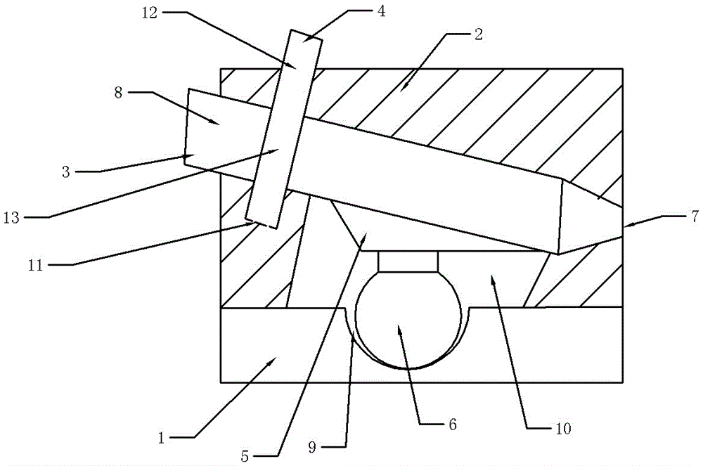
[0010] The reference signs in the drawings of the description include: base 1, clamp body 2, clamping shaft 3, positioning pin 4, fastening block 5, workpiece 6, first mounting hole 7, second mounting hole 8, first concave Groove 9, second groove 10.

[0011] A mold processing fixture, comprising a base 1 and a clamp body 2, the base 1 and the clamp body 2 are fixedly connected, the base is provided with a first groove 9, and the inner wall of the first groove 9 is an arc surface, increasing The contact area between the spherical surface of the workpiece 6 and the first groove 9, the chuck body is provided with a second groove 10, and the first groove 9 and the second groove 10 constitute a cavity for placing the workpiece 6, and the chuck body 2 is provided with a first groove 10. Mounting hole 7, second mounting hole 8, clamp body 2 is provided with clamping shaft 3, clamping shaft 3 passes through the second mounting hole 7 and is against the bottom of the first mounting ho...


PUM


Abstract

A mould processing clamp is characterized by comprising a base and a clamp body, and the base and the clamp body are fixedly connected; the base is provided with a first groove, the clamp body is provided with a second groove, and the first groove and the second groove form a cavity for containing work-pieces; the clamp body is provided with a first installation hole, a second installation hole and a clamping shaft; the clamping shaft penetrates through the second installation hole for abutting against the bottom of the first installation hole, is matched with the second installation hole and the first installation hole in a sliding mode, is inclined and is provided with a fastening block, the fastening block abuts against the work-pieces, and the surface, abutting against the work-pieces, of the fastening block is a horizontal surface; the clamp body is provided with a locating pin for fixing the clamping shaft. The mould processing clamp is simple in structure and can improve the mould processing accuracy.

Description

technical field [0001] The invention belongs to the field of mold processing, and in particular relates to a mold processing fixture. Background technique [0002] In the current process of rapid economic and social development, product updates are accelerating, and market competition is fierce. The processing of molds requires not only improved precision, lower costs, but also simple structure, high production efficiency, and shortened processing time. However, due to the wide variety of molds, different processing tools are required for processing, especially in the processing of some small workpieces with a hemisphere at the bottom and a cylinder at the top. Because the workpiece is too small and has different shapes, the existing technology cannot effectively fix this kind of mold. Most of the workpieces are fixed by manual tweezers, but when the processing machine is processing the workpiece, the pressure is very high, and the manual use of tweezers to fix the workpiece...

Claims


Application Information

Patent Timeline
Patent Type & Authority Applications(China)
IPC IPC(8): B23Q3/06
CPCB23Q3/062
Inventor 王洪
Owner 重庆天和玻璃有限公司
Why Eureka
Try Eureka