
Positive pressure sampling system and positive pressure sampling pump station for sampling system

A technology of positive pressure sampling and pressurized pumps, which is applied in the direction of sampling devices, etc., can solve the problems of slow gas movement speed, etc., and achieve the effects of ensuring no-load start-up, avoiding mixed pollution, and reasonable structural design

Active Publication Date: 2018-04-24
淄博祥龙测控技术有限公司
View PDF5 Cites 0 Cited by
  • Summary
  • Abstract
  • Description
  • Claims
  • Application Information

AI Technical Summary

Problems solved by technology

[0009] The invention realizes the positive pressure delivery of the gas sample through the booster pump, realizes the long-distance fast delivery of the gas in the bundle tube monitoring system, and solves the problem of slow gas movement caused by the traditional negative pressure pumping. There will be slight leakage in some parts, and no outside air will be sucked into the pipeline, thereby avoiding the mixed pollution of gases and ensuring the monitoring results; the pressure relief device can timely release the gas in the pump body when the booster pump stops working. discharge, so as to ensure the smooth start-up of the subsequent booster pump without load, safe and reliable, especially suitable for operations in flammable and explosive environments such as underground mines; through the automatic water filter discharger, the automatic discharge of separated water after gas compression can be realized, thereby realizing Dry pretreatment of sampled gas to ensure dry delivery of sampled gas

Method used


Image

  • Positive pressure sampling system and positive pressure sampling pump station for sampling system
  • Positive pressure sampling system and positive pressure sampling pump station for sampling system

Examples


Embodiment Construction

[0027] Embodiments of the present invention are further described below in conjunction with accompanying drawings:

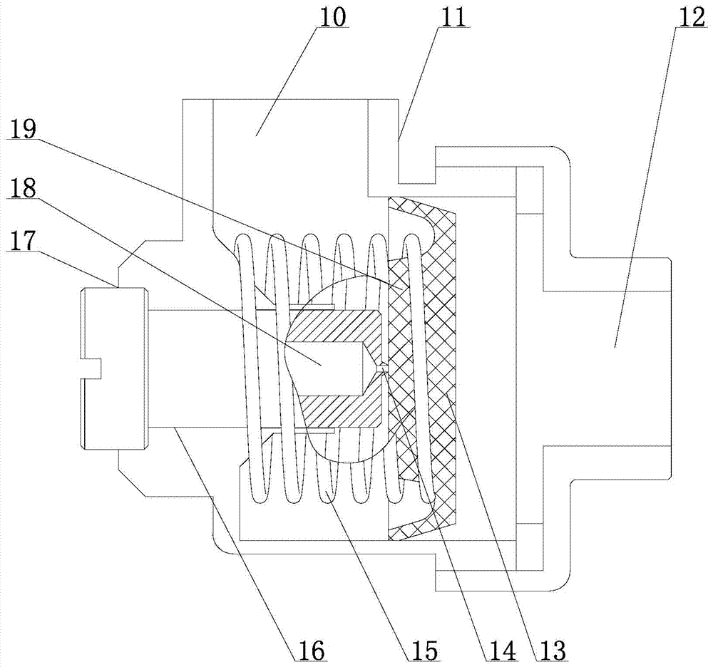
[0028] Such as figure 1 As shown, the positive pressure sampling system of the present invention includes a dust filter 3, a booster pump 4, a pressure relief device 5, a check valve 8 and an automatic water filter discharger 6, a gas input port 1 and a dust filter 3 The air inlet of the dust filter 3 is connected to the inlet of the pressure pump 4, the outlet of the pressure pump 4 is connected to the air inlet 12 of the pressure relief device 5, and the air outlet 10 of the pressure relief device 5 is connected to the air inlet of the pressure relief device 5. The inlet end of the automatic water filter drainer 6 is connected, the gas outlet end of the automatic water filter drainer 6 is connected with the inlet end of the check valve 8, and the gas outlet end of the check valve 8 is connected with the gas output port 9; also includes A one-way valve 7, the ...


PUM


Abstract

The invention belongs to the field of beam tube monitoring, and particularly relates to a positive pressure sampling system. The positive pressure sampling system comprises a pressure pump, a pressure relief device and an automatic filtered water drainer. An inlet of the pressure pump is connected with a gas inlet, and an outlet of the pressure pump is connected with a gas inlet of the pressure relief device. A gas outlet of the pressure relief device is connected with the gas inlet end of the automatic filtered water drainer. The gas outlet end of the automatic filtered water drainer is connected with a gas outlet. A check valve is installed on a pipeline between the gas outlet and the gas outlet end of the automatic filtered water drainer. Remote and rapid conveying of gas of the beam tube system is achieved, gas mixed pollution can be avoided, and the monitoring result is ensured; due to the pressure relief device, gas inside a pump body can be exhausted when the pressure pump stops working, it is ensured that no load is formed when the pressure pump is started again, and use is safe and reliable. The invention further relates to a positive pressure sampling pump station for the sampling system. The positive pressure sampling pump comprises at least two sets of the positive sampling systems, and multi-way sampling gas conveying is achieved.

Description

technical field [0001] The invention relates to a positive pressure sampling system and a positive pressure sampling pump station used for the sampling system, belonging to the field of bundle tube monitoring. Background technique [0002] In recent years, coal mine safety bundle tube monitoring system has been more and more popular and applied in coal mines. [0003] The mine safety bundle tube monitoring system uses the bundle tube to extract and summarize the air from all over the mine to the designated place, and then uses the chromatographic monitoring device to analyze the air samples collected by the bundle tube to realize the detection of CO, CO 2 、CH 4 、C 2 h 4 、C 2 h 6 , O 2 , N 2 On-line monitoring of gas content, the analysis results can be automatically stored in the database while providing data in two ways: real-time monitoring report and daily analysis, so as to analyze the changing trend of a certain gas content in the future, thus realizing Early pr...

Claims


Application Information

Patent Timeline
Patent Type & Authority Patents(China)
IPC IPC(8): G01N1/24
CPCG01N1/24
Inventor 白光星白念祥
Owner 淄博祥龙测控技术有限公司
Learn More