
A sealing method for cracked rock mass resistant to high seepage pressure under shearing action

A fractured rock mass and high permeability resistance technology, applied in the direction of applying stable tension/pressure to test material strength, permeability/surface area analysis, measuring devices, etc., can solve problems that cannot reflect the mechanical properties of fractured rock mass, and achieve measurement Convenient steps, accurate and reliable measurement results

Active Publication Date: 2018-03-16
BEIJING RES INST OF URANIUM GEOLOGY
View PDF4 Cites 0 Cited by
  • Summary
  • Abstract
  • Description
  • Claims
  • Application Information

AI Technical Summary

Problems solved by technology

[0004] The technical problem to be solved in the present invention is: the sealing method of the existing fractured rock mass that can withstand high osmotic pressure under the action of shearing only reflects the permeability of the fractured rock mass inside the cavity under different mechanical effects, and cannot reflect the Mechanical properties of fractured rock mass itself under mechanical action

Method used


Image

  • A sealing method for cracked rock mass resistant to high seepage pressure under shearing action
  • A sealing method for cracked rock mass resistant to high seepage pressure under shearing action
  • A sealing method for cracked rock mass resistant to high seepage pressure under shearing action

Examples


Embodiment 1

[0026] A sealing method for a fractured rock mass resistant to high osmotic pressure under shearing in this embodiment comprises the following steps:

[0027] Step 1. Device Layout

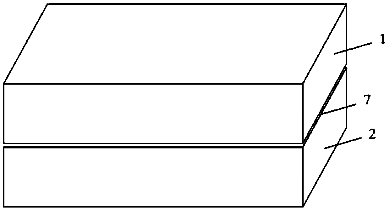
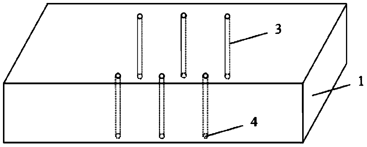
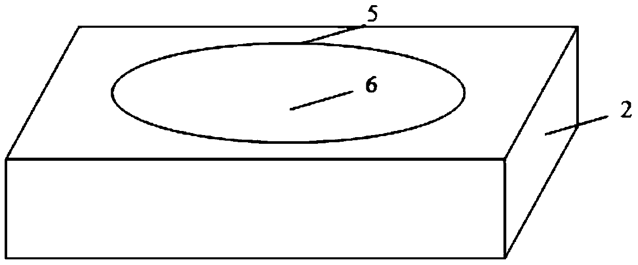
[0028] Such as figure 1 As shown, two rock masses of the same material are stacked up and down, and the lower surface of the upper fractured rock mass 1 and the upper surface of the lower fractured rock mass 2 form a contact surface 7; the upper surface of the lower fractured rock mass 2 is provided with a circle of concave Groove, the seal ring 5 is placed in the groove; several through holes 3 are drilled up and down inside the upper fractured rock mass 1, and the lower end faces 4 of the through holes 3 are included in the area surrounded by the seal ring 5 of the lower cracked rock mass 2 .

[0029] Step 2. High osmotic pressure resistant seal under shear action

[0030] Water flows in from part of the through hole 3 of the upper fractured rock mass 1, seeps inside the sealing ring 5 of the...

Embodiment 2

[0033] The difference between this embodiment and embodiment 1 is:

[0034] Such as figure 2 As shown, the through holes 3 of the upper fractured rock mass 1 are distributed in a matrix inside the upper fractured rock mass 1 .

Embodiment 3

[0036] The difference between this embodiment and the above two embodiments is:

[0037] The roughness of the upper and lower fissure medium contact surfaces 7, the surface roughness of the groove of the sealing ring 5 and the surface roughness of the water flow medium inside the sealing ring 5 are all in the range of 0-1.6; the diameter of the sealing ring 5 ranges from 0.3m -0.6m.


PUM

PropertyMeasurementUnit
diameteraaaaaaaaaa

Abstract

The invention belongs to the technical field of liquid medium water pressure measurement, and in particular relates to a sealing method for cracked rock mass resistant to high osmotic pressure under shearing action. In the method of the present invention, two pieces of fissure media of the same material are stacked up and down, and a sealing ring is provided on the contact surface of the two, water flow flows in / out from the through hole of the upper fissure medium, and a seepage area is formed inside the sealing ring of the contact surface. The invention solves the technical problem that the prior art can only reflect the permeability performance of the cracked rock mass inside the cavity, and the sealing ring on the upper surface of the lower cracked rock mass can ensure that the water flow is always sealed inside the area during the test process, and the permeability test The results can accurately reflect the mechanical properties of the fractured rock mass itself under mechanical action, and are suitable for the high-osmotic pressure-resistant sealing of the fractured rock mass at or above the meter level.

Description

technical field [0001] The invention belongs to the technical field of water pressure measurement in fissure media, and in particular relates to a sealing method for a fissure rock mass resistant to high osmotic pressure under shearing action. Background technique [0002] The water seepage test of the fractured medium under a certain loading pressure is the basic mechanical property test of the fractured medium. The permeability coefficient of fractured media, water pressure test and related research belong to the research category of basic mechanical properties of fractured media, which play a fundamental guiding role in the study of permeability characteristics of fractured media under different working conditions. For quasi-brittle rock materials with fractures, the permeability is an important factor to determine the long-term safety of engineering rock mass. The permeability parameters for evaluating the long-term stability of engineering rock mass are obtained throug...

Claims


Application Information

Patent Timeline
Patent Type & Authority Patents(China)
IPC IPC(8): G01N15/08G01N3/12
Inventor 苏锐满轲王驹
Owner BEIJING RES INST OF URANIUM GEOLOGY
Learn More