Adaptive closed fixture for live working insulator of power transmission line

A technology for live work and transmission lines, applied in the direction of overhead lines/cable equipment, etc., which can solve problems such as inability to replace, inconsistent size of carrying tools, time-consuming and labor-intensive work, etc.

CN105470861AActive Publication Date: 2016-04-06STATE GRID ZHEJIANG ELECTRIC POWER CO LTD JIAXING POWER SUPPLY CO
6 Cites 6 Cited by

Patent Information

Authority / Receiving Office
CN · China
Patent Type
Applications(China)
Current Assignee / Owner
Publication Date
2016-04-06

Smart Images

  • Figure 1
    Figure 1
  • Figure 2
    Figure 2
  • Figure 3
    Figure 3
Patent Text Reader

Abstract

The invention provides an adaptive closed fixture for a live working insulator of a power transmission line. The adaptive closed fixture mainly comprises a front clamping body, a rear clamping body, a front clamping cover and a rear clamping cover, wherein the front clamping body and the rear clamping body are applied to front and rear steel caps of the insulator respectively; the front clamping cover and the rear clamping cover are matched with the front clamping body and the rear clamping body respectively; the front clamping body and the front clamping cover, and the rear clamping body and the rear clamping cover are connected together through pin shafts at one end respectively; semi-arc grooves with the same radius are formed between the front clamping body and the front clamping cover, and between the rear clamping body and the rear clamping cover respectively; a round bayonet capable of clamping the steel caps of the insulator is formed in the middle when the front clamping body and the front clamping cover, and the rear clamping body and the rear clamping cover are hinged into a whole respectively; the other ends of the front clamping body and the front clamping cover, and the rear clamping body and the rear clamping cover are connected with clamping bolts with fixing nuts through the pin shafts respectively; and in the round bayonet in the middle of the front clamping body, the front clamping cover, the rear clamping body and the rear clamping cover, a large inclined plane is arranged at least from one side surface to the other side surface and a large reducing tapered bayonet is formed.
Need to check novelty before this filing date? Find Prior Art

Description

technical field

[0001] The invention relates to a self-adaptive closed clamp for live working insulators of transmission lines, which is used for replacing insulators of different manufacturers and types on high-voltage transmission lines, and belongs to the technical field of maintenance tools for overhead transmission lines. Background technique

[0002] When replacing the insulator on the transmission line, it is necessary to prepare corresponding tools according to different manufacturers and different types of insulators. When the tools and tools carried do not match the specifications and sizes of the replaced insulators, the replacement operation will not be possible and other specifications need to be replaced. The size of tools and utensils puts forward higher requirements for the preparatory work of the operation. At the same time, when the size of the portable tools and utensils does not match, it needs to be replaced in time, and the work is time-consuming and lab...

Examples

Embodiment Construction

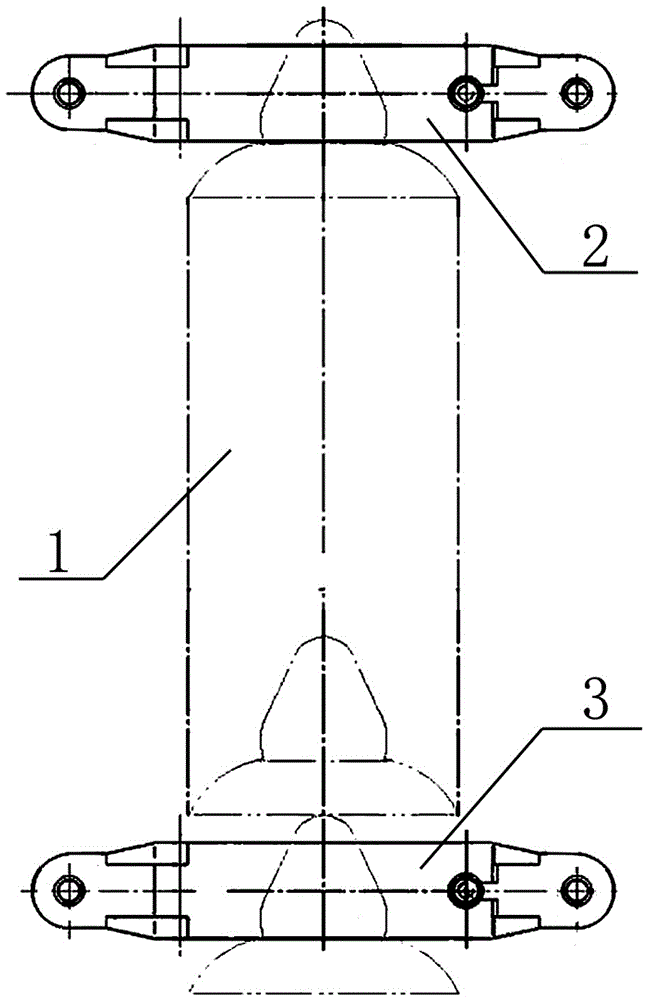
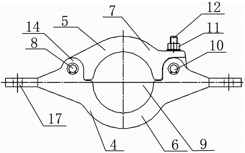
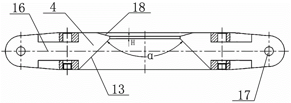
[0014] The present invention will be described in detail below in conjunction with accompanying drawing: figure 1 As shown in the present invention, a self-adaptive closed clamp for live working insulators of transmission lines mainly includes a front clamp body and a rear clamp body respectively used on the front and rear steel caps of the insulator 1, and the front clamp body and the front clamp body respectively. The front card cover and the rear card cover that match the body and the rear card body, and constitute the front clamp 2 and the rear clamp 3 respectively; the front card body 4 and the front card cover 5, the rear card body 6 and the rear card cover 7 Respectively connected together through the pin shaft 8 at one end, see figure 2 shown; and the middle of the front card body 4 and the front card cover 5, the rear card body 6 and the rear card cover 7 are respectively provided with semicircular arc grooves of the same radius, and in the front card body 4 and the ...