Good-quality mold for forming ventilating slippers
A technology of quality and slippers, which is applied to household appliances, other household appliances, household components, etc., can solve the problems that affect the ventilation effect and quality of finished slippers, and the air holes and horizontal air holes are not connected, so as to achieve strong practicability and novel structure Reasonable and efficient ventilation effect
- Summary
- Abstract
- Description
- Claims
- Application Information
AI Technical Summary
Problems solved by technology
Method used
Image

Examples
Embodiment Construction
[0019] In order to further explain the technical solutions of the present invention, specific examples are given below to illustrate in detail.
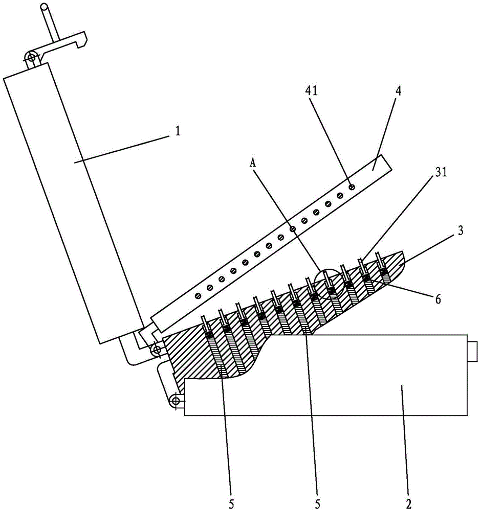
[0020] A kind of mold of good quality of forming ventilated air-permeable slipper of the present invention, as figure 1 and 2 As shown, it includes an upper template 1 with an upper cavity, a lower template 2 with a lower cavity, a shoe-last-shaped core 3 between the upper template 1 and the lower template 2, and a shoe-last-shaped mold The horizontal air hole template 4 between the core 3 and the upper template 1.
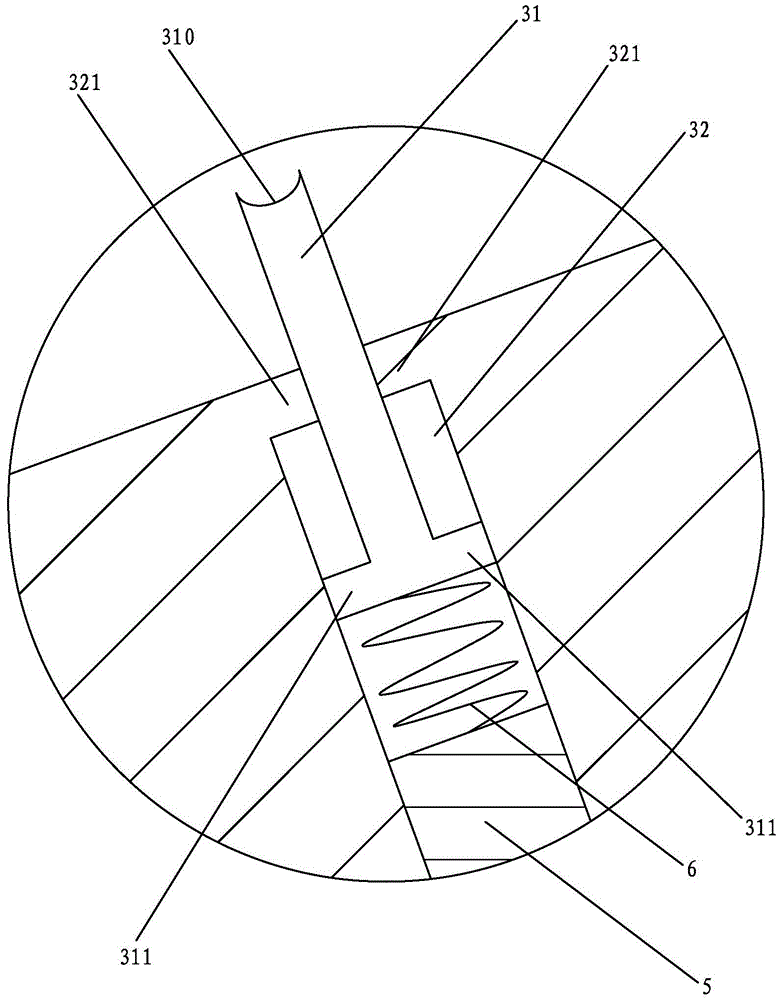
[0021] The rear edge of the shoe-last-shaped mold core 3 is hinged to the lower template 2, and the rear edge of the upper template 1 is hinged to the shoe-last-shaped mold core 3. The upper surface of the shoe-last-shaped mold core 3 is evenly distributed with rows of air holes arranged in parallel to form columns 31. The horizontal air hole template 4 includes a left template and a right template that are spliced t...
PUM
 Abstract
Description
Claims
Application Information
PatSnap Eureka turns technology decisions into work you can execute. Powered by our Innovation Knowledge Graph, it runs expert workflows across engineering, life sciences, materials and intellectual property. Get your review-ready output in minutes.


