
An intelligent bin loading machine

An intelligent, rack-based technology, applied in the direction of conveyor, loading/unloading, transportation and packaging, etc., can solve the problems of time waste, dust diffusion, inconvenient equipment operation, etc., and achieve simple and convenient operation, flexible movement and labor saving Effect

Active Publication Date: 2017-05-10
HEBEI PINGLE FLOUR MACHINERY GROUP
View PDF8 Cites 0 Cited by
  • Summary
  • Abstract
  • Description
  • Claims
  • Application Information

AI Technical Summary

Problems solved by technology

[0003] However, there are generally some technical defects in the existing bin loading machines. At present, the conveying part of the traditional bin loading machine generally cannot rotate left and right, and some conveying parts can rotate without setting a reasonable rotating structure. Human propulsion brings inconvenience to the operation of the equipment, and the safety is poor; the existing bin loading machines are fixed and movable, and the fixed bin loading machine can only be used in a specific place, and the scope of application is small. The movable binning machine is limited by the load and stability of the wheels, so it cannot quickly transport and bin a large amount of materials; the switch operation panel of the existing binning machine is installed on the machine base, and workers operate each Every action must be close to the equipment. When the operator stands next to the equipment operation panel to operate, there will be a large range of blind spots in the field of vision. In order to operate safely and effectively, more than three people must cooperate to carry out the operation, which takes up too much space. Personnel also increases unsafe factors; in this operation process, the bin loading machine needs to frequently adjust its actions, such as the height adjustment of the conveyed materials, the left and right angle swing of the bin loading machine, and even the forward and backward of the entire equipment. Almost in the entire operation process, the operator needs to operate the whole process and at close range, which will cause harm to the health of the staff; there are several ways for the existing bin loading machine to move the whole machine: relying on other power traction, relying on Push it manually or rely on its own geared motor to provide power to move
All these methods require the introduction of external power to move the equipment. Every time the equipment moves, especially for long-distance movement, it is very cumbersome; the operating system of the existing bin loading machine is only a set of operating systems installed on the base , there is no backup system, once there is a problem with the operating system during the working process, it will cause a lot of time wasting and economic loss; during the working process of the bin loading machine, in order to maintain the balanced operation of the equipment, it is generally necessary to set a counterweight, generally Sand, cement blocks or stones are used as counterweight materials, because the specific gravity of sand, cement and stones is small, in order to achieve the required counterweight weight, it is necessary to add a large amount of cement or stones, resulting in a large volume of the counterweight bin, and then As a result, the volume of the entire equipment increases, and unreasonable counterweight settings also cause potential safety hazards; at present, the transmission belts of the transmission mechanism of the bin loading machine are all fixed strokes, and each adjustment of different strokes requires dismantling the rollers and reinstalling the conveyor belt , time-consuming and labor-intensive; all parts of the conveyor of the existing binning machine are open structures that are visible from the conveyor belt. These flying dust cannot be limited within a certain space range, causing the dust to spread around and causing harm to the surrounding working environment and operators; the base of the existing bin loading machine and the transmission mechanism are connected as one, and the angle cannot be adjusted at any time. The height of the conveyed material cannot be changed

Method used


Image

  • An intelligent bin loading machine
  • An intelligent bin loading machine
  • An intelligent bin loading machine

Examples


Embodiment Construction

[0026] The present invention will be described in further detail below in conjunction with the accompanying drawings.

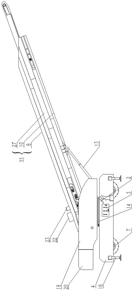
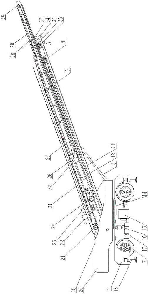
[0027] as attached Figure 1-6As shown, an intelligent binning machine includes a fixed base 4, a rotating base 19 that can rotate horizontally on the fixed base 4, a conveying mechanism that is arranged on the front of the rotating base 19, and a conveyor that is arranged on the fixed base 4. A power control mechanism for controlling the rotation of the rotating base 19 and the conveying mechanism for conveying materials. A turntable 14 is provided between the rotating base 19 and the fixed base 4, and the turntable 14 is a slewing support bearing. Walkable wheels 7 and supporting legs 18 supported on the ground are arranged under the fixed base 4 . The power control mechanism includes a rotary hydraulic motor 16 arranged on the fixed base 4 to control the rotation of the turntable 14, a travel hydraulic motor 5 for driving the wheels 7 to travel, a hydrau...


PUM


Abstract

The invention discloses an intelligent binning machine. The intelligent binning machine comprises a fixed base, a rotary base which is arranged on the fixed base and can horizontally rotate, a conveying mechanism arranged on the front portion of the rotary base and a power control mechanism which is arranged on the fixed base and used for controlling the rotary base to rotate and the conveying mechanism to convey materials. The conveying mechanism can rotate conveniently in a multi-angle manner, walking is flexible, and supporting is stable; in the processes of moving, rotating, angle adjusting and conveying belt stretching and contracting, operation can be completed only through one operator; no visual blind area exists, the safety of the operators and equipment is comprehensively guaranteed, the operator can carry out operation by being away from the binning machine, and a large amount of generated dust is prevented from harming the health of the operator; and operation through a remote control unit is adopted as the main operation means, an electric disc operation system arranged on the bases is adopted as the auxiliary and standby operation means, and in the binning work process, the situation that work is interrupted for maintenance, and consequently time and economic losses are caused is avoided.

Description

technical field [0001] The invention relates to the technical field of grain processing machinery and equipment, in particular to an intelligent bin loading machine. Background technique [0002] In the prior art, when grain is loaded into bins, etc., it is usually done by manual manual labor, and the work efficiency is low. With the development of science and technology, some bin loading machines used in the grain processing industry came into being. After the grain is transported to the gate of the grain depot by the transport vehicle, it is unloaded on the grain receiving machine, cleaned and then transported to the belt conveyor, and then transported by the belt. The binning machine is generally suitable for the transportation of bulk grain and other granular materials. The binning machine can move inside or outside the warehouse for bulk grain entering the warehouse. [0003] However, there are generally some technical defects in the existing bin loading machines. At p...

Claims


Application Information

Patent Timeline
Patent Type & Authority Patents(China)
IPC IPC(8): B65G65/32B65G69/18B65G69/20B65G21/12
CPCB65G21/12B65G65/32B65G69/182B65G69/20B65G2201/04
Inventor 李建军吴军永张立建高鹏周锋
Owner HEBEI PINGLE FLOUR MACHINERY GROUP
Learn More