Molding method of integrated cold shield for infrared detector

A technology of infrared detector and molding method, which is applied in the field of materials, can solve the problems that are not conducive to the life of Dewar vacuum, cannot complete the integrated molding process, and the detector Dewar vacuum fails, so as to achieve the effect of maintaining a long life of vacuum

Active Publication Date: 2016-04-13
11TH RES INST OF CHINA ELECTRONICS TECH GROUP CORP
View PDF7 Cites 2 Cited by
  • Summary
  • Abstract
  • Description
  • Claims
  • Application Information

AI Technical Summary

Problems solved by technology

[0002] At present, the life expectancy of the second-generation and third-generation cooled infrared focal plane detector components is generally about 15 years. The main factor affecting its life is the vacuum life of the detector micro-Dewar, and the vacuum life of the Dewar mainly depends on the package. For the outgassing of various internal parts (including detector chips, cold screens, ceramic substrates and optical filters, etc.), due to the electrical lead-out and low-temperature working characteristics, low-temperature epoxy bonding is used between each part The organic epoxy glue will slowly decompose in a high vacuum environment to form various small molecular gases such as H2, H2O

Method used


Image

  • Molding method of integrated cold shield for infrared detector
  • Molding method of integrated cold shield for infrared detector

Examples


Embodiment Construction

[0024] Preferred embodiments of the present invention will be specifically described below in conjunction with the accompanying drawings, wherein the accompanying drawings constitute a part of the application and are used together with the embodiments of the present invention to explain the principle of the present invention. For the sake of clarity and simplicity, detailed descriptions of known functions and constructions in the devices described herein will be omitted when it may obscure the subject matter of the present invention.

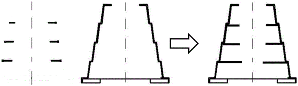
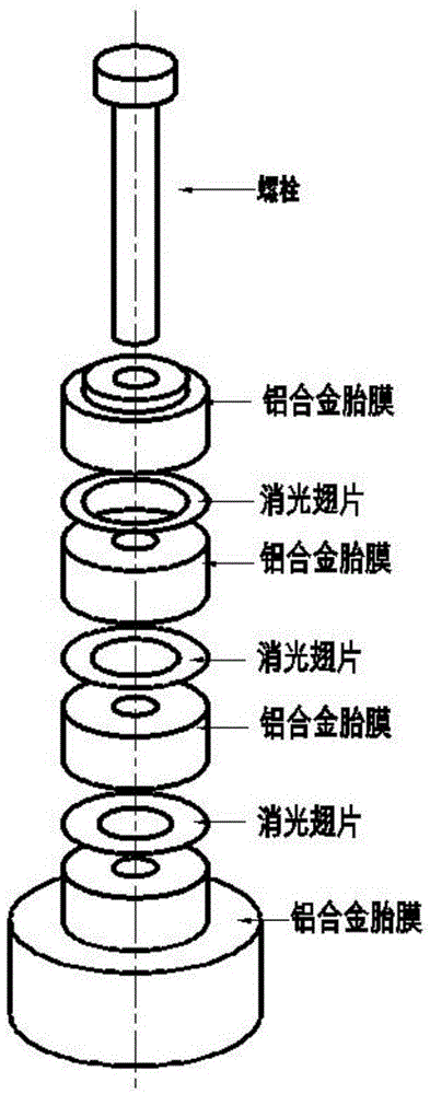
[0025] In order to solve the problem that excessive glue is introduced into the fin bonding process in the prior art, thus reducing the vacuum life of the Dewar, the present invention provides a method for forming an integrated cold screen for infrared detectors. Due to the extinction of the electroformed cold screen of the present invention The fins are integrated with the outer wall material without welding seams, glue joints and screw threads....


PUM


Abstract

The invention discloses a molding method of an integrated cold shield for an infrared detector. Extinction fins of the cold shield are directly electro-casted with a cold shield body, secondary bonding is avoided, glue for packaging is effectively controlled, the vacuum service life of the detector can be maintained for long time; and design of the cold shield body is simplified, bonded fitting and positioning surfaces are not embodied in the cold shield body, the total weight of the cold shield is decreased, power requirement for a refrigerator is lowered, and work of the cold shield is higher.

Description

technical field [0001] The invention relates to the field of material technology, in particular to a method for forming an integrated cold screen for an infrared detector. Background technique [0002] At present, the life expectancy of the second-generation and third-generation cooled infrared focal plane detector components is generally about 15 years. The main factor affecting its life is the vacuum life of the detector micro-Dewar, and the vacuum life of the Dewar mainly depends on the package. For the outgassing of various internal parts (including detector chips, cold screens, ceramic substrates and optical filters, etc.), due to the electrical lead-out and low-temperature working characteristics, low-temperature epoxy bonding is used between each part The organic epoxy glue will slowly decompose in a high vacuum environment to form various small molecular gases such as H2, H2O, and CO, which will eventually cause the vacuum in the detector Dewar to fail. As an import...

Claims


Application Information

Patent Timeline
IPC IPC(8): G01J5/02
CPCG01J5/02
Inventor 卢加涛孟令伟
Owner 11TH RES INST OF CHINA ELECTRONICS TECH GROUP CORP
Why Eureka
Try Eureka