Supercharge Your Innovation With Domain-Expert AI Agents!

Method for activating a deflection device of a projection device, projection device and deflection device thereof

A deflecting device, projection device technology, applied in projection devices, color TV parts, optics, etc., can solve problems such as high amplitude

Active Publication Date: 2018-03-30
FRAUNHOFER GESELLSCHAFT ZUR FOERDERUNG DER ANGEWANDTEN FORSCHUNG EV
View PDF5 Cites 0 Cited by
  • Summary
  • Abstract
  • Description
  • Claims
  • Application Information

AI Technical Summary

Problems solved by technology

In most cases, such a scanner can only generate high amplitudes if it operates resonantly

Method used


Image

  • Method for activating a deflection device of a projection device, projection device and deflection device thereof
  • Method for activating a deflection device of a projection device, projection device and deflection device thereof
  • Method for activating a deflection device of a projection device, projection device and deflection device thereof

Examples


Embodiment Construction

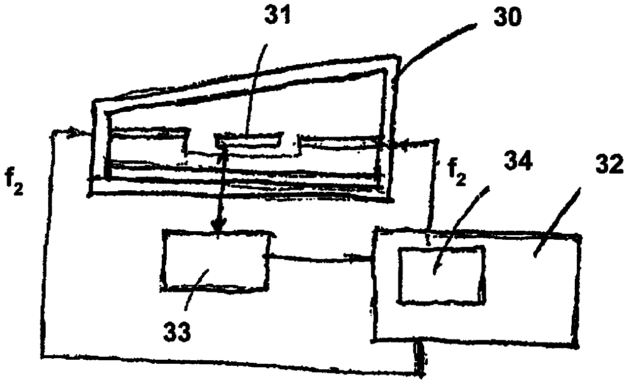
[0081] in figure 1 Here, the deflection unit is schematically indicated as 30, which serves as the deflection element 31 and includes a two-axis cardanically suspended micromirror 31. For each axis, at frequency f1 and frequency f2 and the activation amplitudes A1 and A2, the deflection element or micromirror 31 (whose drive is not shown in detail) is driven by the activation signal sent from the activation device 32, and the frequency f1 and frequency f2 are used as Activate the signal.

[0082] The activation device 32 includes a control loop 34 designed to perform closed-loop control of the activation signal. figure 1 The control loop 34 shown in is only schematically shown for two shafts, but a control loop may be provided for each oscillation shaft. A measuring device 33 that measures the deflection of the micromirror 31 is provided for detecting the amplitude or phase position of the oscillation. The amplitude or phase position of the oscillation can be detected by an op...


PUM


Abstract

The invention relates to a method for activating a deflection device (22) comprising at least one deflection unit (30), a projection device for projecting a trajectory onto a projection surface (24), wherein the deflection means (22) deflect electromagnetic radiation directed thereon to generate a trajectory, and at least one deflection unit (30) is activated by an activation signal sent from the control means (32) to generate oscillations, in each case A rotational amplitude around at least one direction of the deflection axis at a change in direction of oscillation, wherein in the case of resonance the oscillation has a maximum amplitude at which the resulting trajectory reaches the edge of the projection surface (24). The activation signal is arranged in such a way that the rotational amplitude of the oscillations has at least temporarily a predetermined value outside the region of the maximum amplitude of the oscillations, and an intensity distribution of the generated trajectory on the projection surface ( 24 ) with a predetermined intensity pattern is achieved. The invention also relates to a deflection device (22) and a projection device.

Description

Technical field [0001] The invention relates to a method for activating a deflection device of a projection device, a deflection device and a projection device. Background technique [0002] The so-called Lissajous projector is known as the prior art, in which a mirror that resonates or almost resonates in two axes to vibrate sinusoidally is used. In this principle, these mirrors, also denoted as resonant scanners, can achieve much larger amplitudes than non-resonant operating scanners. Compared with scanning laser projection, it has larger amplitude, which is equivalent to higher optical resolution. [0003] Thus, DE 10 2009 058 762 A1 discloses a deflection device of a projection device for projecting Lissajous figures onto a projection surface. In order to deflect the light beam about at least one first and second deflection axis, the The deflection device is designed to generate Lissajous figures. The deflection device includes a deflection unit for generating an oscillation...

Claims


Application Information

Patent Timeline
Patent Type & Authority Patents(China)
IPC IPC(8): G02B26/10G03B21/14
CPCG02B26/0841G02B26/101G02B27/104H04N9/3135G02B27/0927
Inventor 乌尔里希·霍夫曼弗兰克·森杰托马斯·冯·万托霍克里斯汀·马拉斯乔西姆·简斯曼弗雷德·维贝
Owner FRAUNHOFER GESELLSCHAFT ZUR FOERDERUNG DER ANGEWANDTEN FORSCHUNG EV
Features
  • R&D
  • Intellectual Property
  • Life Sciences
  • Materials
  • Tech Scout
  • Unparalleled Data Quality
  • Higher Quality Content
  • 60% Fewer Hallucinations
Learn More