
Filter cloth fixing structure based on pressing ring and filer plate system using filter cloth fixing structure

A filter press plate and filter cloth technology, which is applied in filtration separation, separation methods, chemical instruments and methods, etc., can solve the problems of a large amount of fixing screws, affecting the working efficiency of the equipment, and inconvenient to replace the filter cloth, so as to achieve the sealing effect. Significantly, improve firmness and stability, and facilitate replacement

Inactive Publication Date: 2016-04-20
FOSHAN JINKAIDI FILTRATION EQUIP CO LTD
View PDF3 Cites 4 Cited by
  • Summary
  • Abstract
  • Description
  • Claims
  • Application Information

AI Technical Summary

Problems solved by technology

However, the filter cloth in the filter plate of the existing filter press is easy to loose after working for a long time, and the amount of fixing screws is large, and it is inconvenient to replace the filter cloth, the replacement is difficult, the maintenance cost is high, and the operation of the equipment is seriously affected. efficiency

Method used


Image

  • Filter cloth fixing structure based on pressing ring and filer plate system using filter cloth fixing structure
  • Filter cloth fixing structure based on pressing ring and filer plate system using filter cloth fixing structure
  • Filter cloth fixing structure based on pressing ring and filer plate system using filter cloth fixing structure

Examples


Embodiment Construction

[0024] The present invention will be further described in conjunction with the following examples.

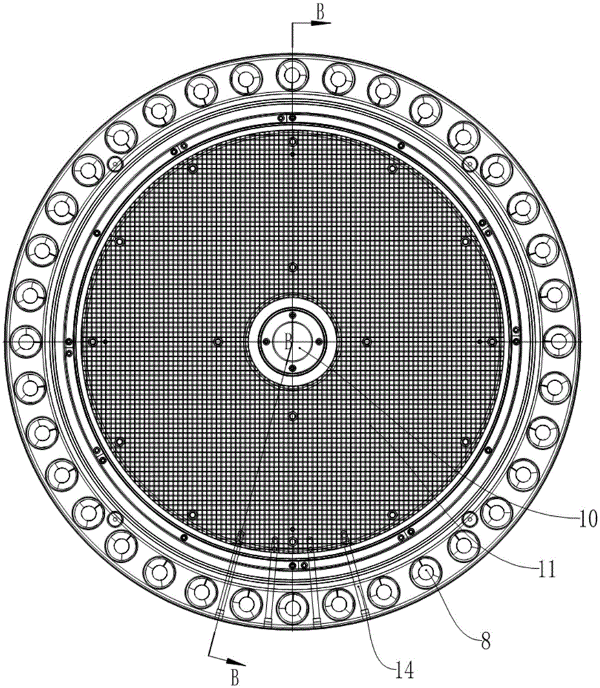
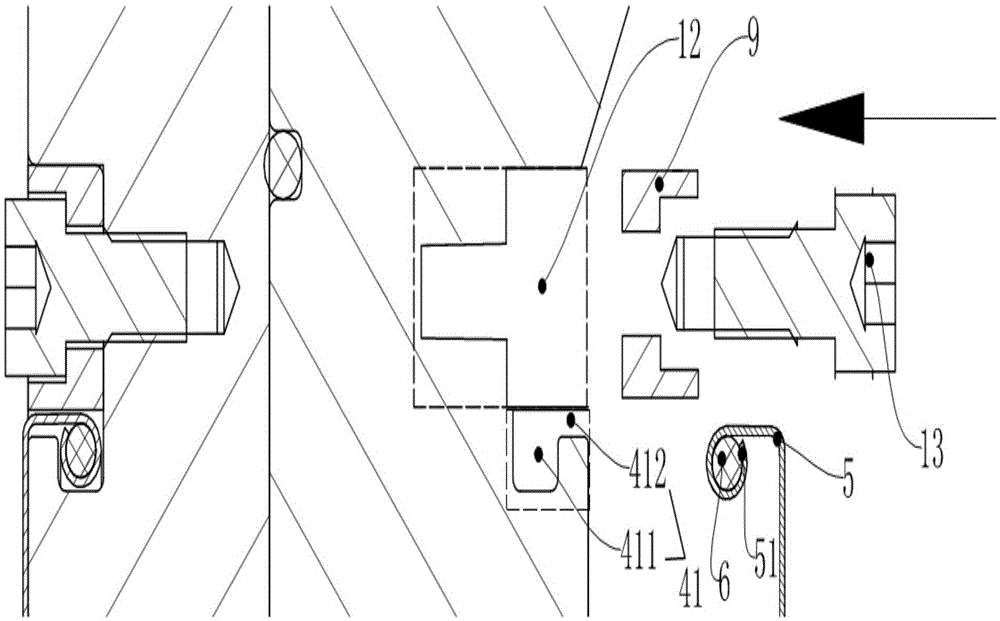
[0025] The fixed filter cloth structure based on the pressure ring of the present embodiment and the filter plate system using it, such as Figure 1-4 As shown, it includes a filter press body and an installation groove, the middle part of the filter press body is provided with a through hole 10, and the installation groove is arranged around the filter press body, and the installation groove includes an outer edge A groove 41 and an inner edge groove 42, the outer edge groove 41 is arranged around the outer edge side of the filter press body, and the inner edge groove 42 is arranged on the inner edge side of the filter press body , and close to the through hole 10; when the installation is completed, the edge portion 51 of the filter cloth 5 is set in the installation groove by the clamping of the filter cloth fixing strip 6, and the filter cloth fixing strip 6 and the filter ...


PUM


Abstract

The invention relates to a filter cloth fixing structure based on a pressing ring and a filter plate system using the filter cloth fixing structure. The filter cloth fixing structure based on the pressing ring comprises a press filter plate body and an installation groove, and a through hole is formed in the middle of the press filter plate body. The installation groove is formed in the press filter plate body in a surrounding mode and comprises an outer edge groove body and an inner edge groove body, the outer edge groove body is formed in the outer edge side of the press filter plate body in a surrounding mode, and the inner edge groove body is formed in the inner edge side of the press filter plate body and is close to the through hole. The installation groove comprises a fixing cavity and a transition cavity, wherein the section width of the fixing cavity is larger than that of the transition cavity, the fixing cavity is formed in the inner side of the installation groove, and the transition cavity is formed in the outer side of the installation groove. By means of the filter cloth fixing structure based on the pressing ring, the stability in the filter cloth installation process is greatly improved, and the phenomenon that filter cloth is likely to loosen due to long-term use is avoided; meanwhile, the filter cloth is convenient to replace, the maintenance cost is low, and the working efficiency of equipment is improved.

Description

technical field [0001] The invention relates to the technical field of filter equipment, in particular to a fixed filter cloth structure based on a pressure ring and a filter plate system using the same. Background technique [0002] In recent years, the country has increasingly higher requirements for environmental protection and resource utilization, and vigorously advocates energy conservation, emission reduction, and clean production. As the main equipment used in the field of environmental protection, filter press is widely used in food, chemical, environmental protection and sewage treatment industries, and the market demand has increased significantly. Current filter presses are provided with grooves on the fronts of the main frame and the sub-frame, and the filter cloth is compressed in the grooves by beading. However, the filter cloth in the filter plate of the existing filter press is easy to loose after working for a long time, and the amount of fixing screws is ...

Claims


Application Information

Patent Timeline
IPC IPC(8): B01D25/176B01D25/12
CPCB01D25/176B01D25/215
Inventor 庞仲达
Owner FOSHAN JINKAIDI FILTRATION EQUIP CO LTD
Learn More