Stirring rod

The technology of stirring rod and stirring blade is applied in the directions of mixer accessories, mixer with rotating stirring device, dissolving, etc., which can solve the problems that the stirring rod cannot cope with various production demands and increase the production cost, and achieves a simple structure, Easy-to-use effects

Inactive Publication Date: 2016-04-20
SUZHOU ZEMEI NEW MATERIAL TECH
View PDF7 Cites 2 Cited by
  • Summary
  • Abstract
  • Description
  • Claims
  • Application Information

AI Technical Summary

Problems solved by technology

As a result, the production costs have increased, and various customized stirring rods cannot cope with various production needs

Method used


Image

  • Stirring rod
  • Stirring rod
  • Stirring rod

Examples


Embodiment Construction

[0013] The specific implementation manners of the present invention will be further described below in conjunction with the drawings and examples. The following examples are only used to illustrate the technical solution of the present invention more clearly, but not to limit the protection scope of the present invention.

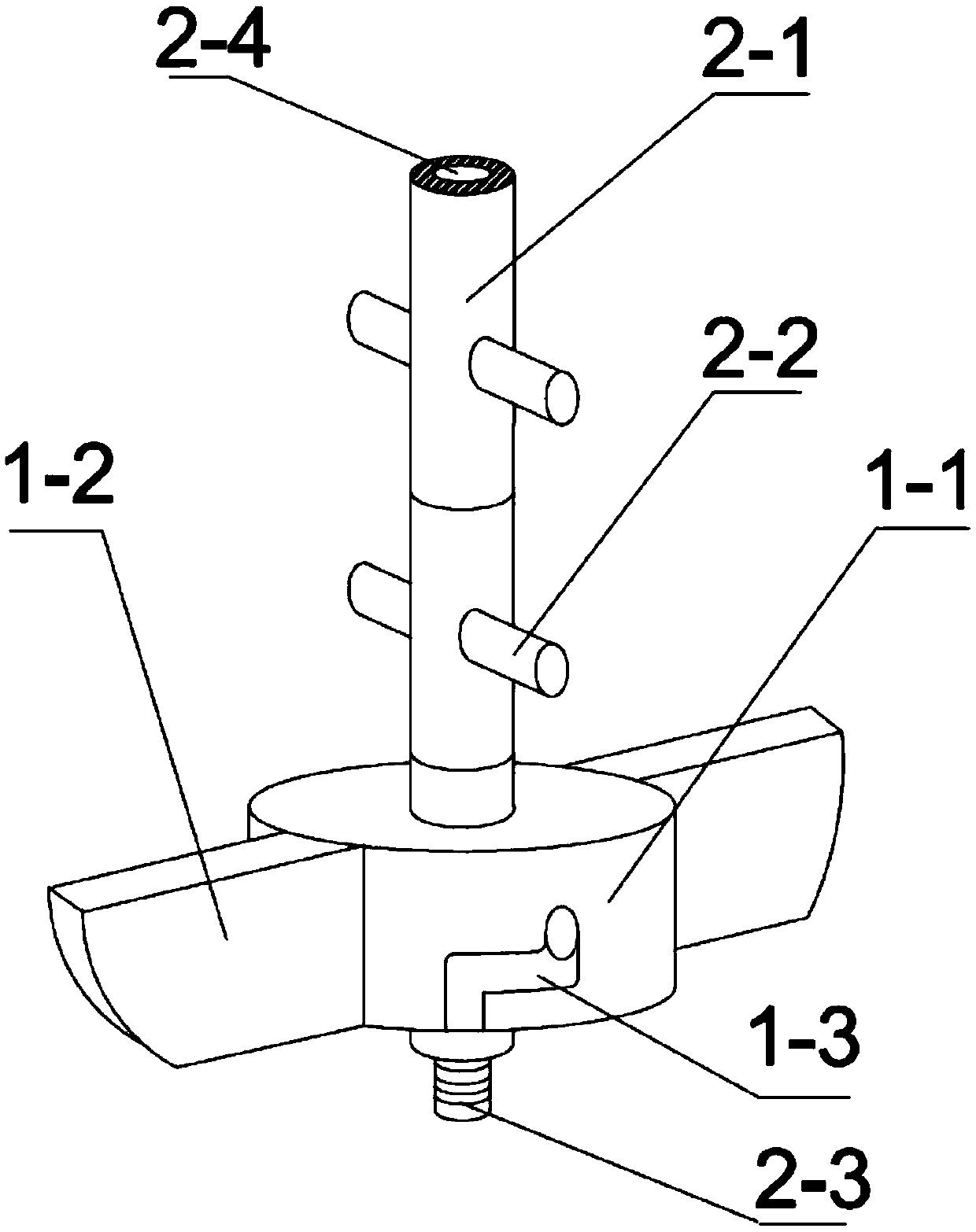
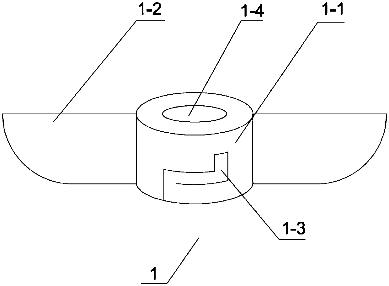
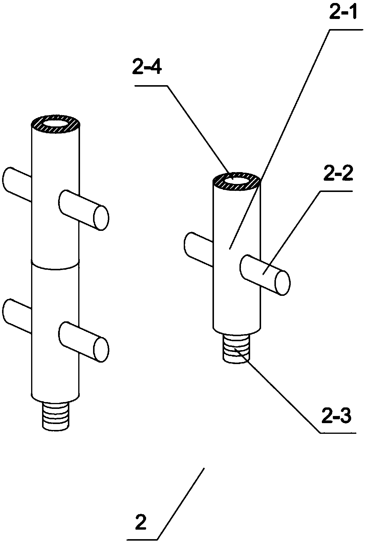
[0014] A stirring rod comprises a stirring paddle 1 and a connecting rod 2. Among them, the stirring paddle 1 includes a paddle body 1-1, a blade 1-2, and a Z-shaped groove 1-3; the central position of the paddle body 1-1 is provided with a through hole 1-4; the Z-shaped groove 1-3 is arranged on The blade main body 1-1 has two front and rear sides; the blade 1-2 is arranged on the left and right sides of the blade main body 1-1; the connecting rod 2 is spliced ​​by three connecting rod splicing pieces; the splicing piece main body 2-1 of the connecting rod splicing piece One end is provided with a blind hole 2-4, and the blind hole 2-4 is provided with an...


PUM


Abstract

The invention discloses a stirring rod. The stirring rod comprises a stirring paddle and a connection rod, wherein the stirring paddle comprises a paddle main body, blades and Z-shaped grooves; a through hole is formed in the central position of the paddle main body; the Z-shaped grooves are formed in the front and back surfaces of the paddle main body; the blades are arranged at the left and right sides of the paddle main body; the connection rod is formed by splicing more than two connection rod splicing parts; a blind hole is formed in a splicing part main body of each connection rod splicing part and internal threads are arranged in each blind hole; a bulge is arranged at the other end of each splicing part main body and external threads are arranged outside the bulge; the bulges are matched with the blind holes in size; the external threads on the bulges are matched with the internal threads in the blind holes; inserting rods are arranged at the two sides of the connection rod splicing parts; the diameter size of each inserting rod is matched with the width size of the corresponding Z-shaped groove. The stirring rod disclosed by the invention can be matched with reaction devices with different sizes through extending or shortening the length of the connection rod and increasing or decreasing the quantity of the stirring paddles according to requirements; the stirring rod is simple in structure and convenient to use.

Description

technical field [0001] The invention relates to a stirring rod. Background technique [0002] In the process of producing chemical products, stirring rods of different sizes are usually used to meet the needs of small test, pilot test or industrial production. As a result, the cost of production has increased, and various customized stirring rods cannot cope with various production needs. Contents of the invention [0003] The object of the present invention is to provide a stirring rod, which can extend or shorten the length of the connecting rod as required, and increase or decrease the number of stirring blades, can match reaction devices of different sizes, has a simple structure and is easy to use. [0004] In order to achieve the above object, the technical solution of the present invention is to design a stirring rod, including stirring paddles and connecting rods. Wherein, the stirring paddle includes a paddle body, a blade, and a Z-shaped groove; a through hole ...

Claims


Application Information

Patent Timeline
Patent Type & Authority Applications(China)
IPC IPC(8): B01F15/00
CPCB01F27/054B01F27/0724B01F27/1163B01F27/112B01F27/2121
Inventor 莫云泽
Owner SUZHOU ZEMEI NEW MATERIAL TECH
Why Eureka
Try Eureka