A palletizing robot

A palletizing robot and rack technology, applied in the field of industrial robots, can solve the problems of complex control and operation, poor dynamic performance, and coupling of component movements, and achieve the effect of flexible and changeable motion trajectories

Active Publication Date: 2017-07-18
GUANGXI UNIV
View PDF11 Cites 0 Cited by
  • Summary
  • Abstract
  • Description
  • Claims
  • Application Information

AI Technical Summary

Problems solved by technology

[0004] The purpose of the present invention is to provide a palletizing robot, so as to overcome the disadvantages of poor dynamic performance, complex control and operation, and coupling of components in the traditional articulated palletizer system

Method used


Image

  • A palletizing robot
  • A palletizing robot
  • A palletizing robot

Examples


Embodiment Construction

[0015] The specific embodiments of the present invention will be described in detail below with reference to the accompanying drawings, but it should be understood that the protection scope of the present invention is not limited by the specific embodiments.

[0016] Unless expressly stated otherwise, throughout the specification and claims, the term "comprising" or its conjugations such as "comprising" or "comprising" and the like will be understood to include the stated elements or components, and Other elements or other components are not excluded.

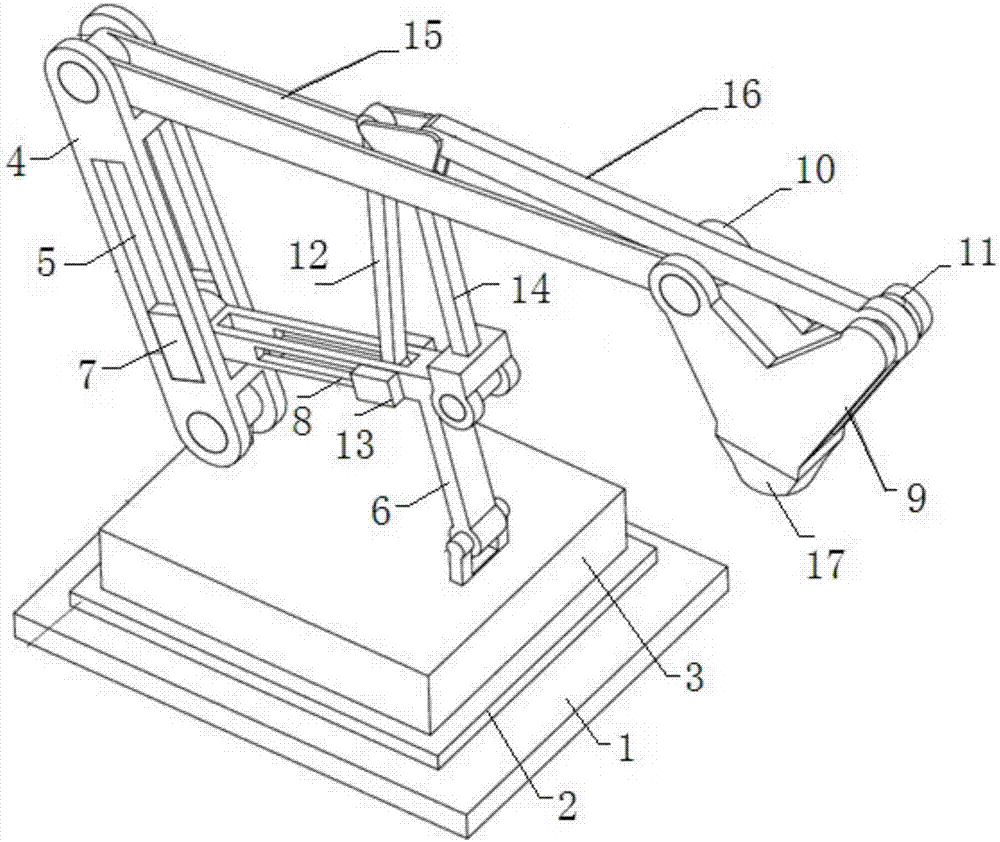
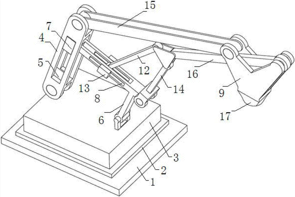
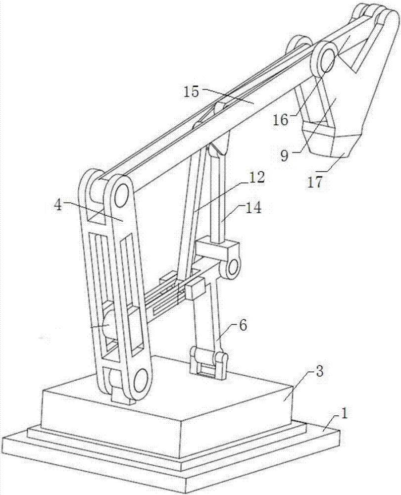
[0017] like Figure 1 to Figure 3 As shown, a palletizing robot according to a specific embodiment of the present invention includes: a base 1, a frame 3, an active rod 4, a T-shaped support rod 6, an actuator 9, a first arm rod 15, and a first link 12 , the second connecting rod 14 and the second arm rod 16; the frame 3 is set on the base 1 through the rotating pair 2; one end of the active rod 4 is hinged on the frame 3 thro...


PUM


Abstract

The invention discloses a stacking robot which comprises a base, a rack, a driving rod, a T-shaped supporting rod, an actuator, a first arm rod, a first connecting rod, a second connecting rod and a second arm rod. The rack can be rotatably arranged on the base. One end of the driving rod is hinged to the rack, and a longitudinal sliding groove is formed in the rod wall of the driving rod. The bottom end of the T-shaped supporting rod is hinged to the rack, the first T-shaped end of the T-shaped supporting rod is arranged in the longitudinal sliding groove, and a transverse sliding groove is formed in the rod wall of the T-shaped supporting rod. The actuator is provided with a first actuating end and a second actuating end. The two ends of the first arm rod are hinged between the first actuating end and the other end of the driving rod. One end of the first connecting rod is arranged in the transverse sliding groove, and one end of the second connecting rod is hinged to the second T-shaped end of the T-shaped supporting rod. One end of the second arm rod is hinged to the second actuating end, and the other end of the second arm rod, the other end of the first connecting rod and the other end of the second connecting rod are hinged to a triangular plate together. The robot has the advantages of being easy to control, large in work space, small in occupied area and the like.

Description

technical field [0001] The invention relates to the field of industrial robots, in particular to a multi-degree-of-freedom palletizing robot. Background technique [0002] With the development of machinery manufacturing industry and changes in packaging types, factory environment and customer needs, palletizing equipment has made great progress in all aspects. At present, the palletizing robots independently researched and developed in my country mainly have right angles There are two types of coordinate type and joint type coordinate type. Among them, the rectangular coordinate type is a 4-axis robot, which corresponds to the X-axis, Y-axis and Z-axis in the rectangular coordinate system, and a rotation axis on the Z-axis. The rectangular-coordinate type robot has high positioning accuracy and space trajectory is easy to solve It has the advantages of large space, small working range, poor flexibility and low movement speed. The articulated robot occupies a small space and...

Claims


Application Information

Patent Timeline
Patent Type & Authority Patents(China)
IPC IPC(8): B25J9/06B65G61/00
CPCB25J9/06B65G61/00
Inventor 周晓蓉徐敏唐伟力金荣鑫王毅
Owner GUANGXI UNIV
Why Eureka
Try Eureka