a stripper

A technology of demoulding and formwork, which is applied in the field of demoulding, can solve the problems of low pass rate, product breakage, appearance scratches, etc., and achieve the effects of increasing shift production, uniform force, and beautiful appearance

Active Publication Date: 2017-10-13
ANHUI DFSEAL RUBBER SHOCK ABSORBER TECH CO LTD
View PDF4 Cites 1 Cited by
  • Summary
  • Abstract
  • Description
  • Claims
  • Application Information

AI Technical Summary

Problems solved by technology

When demoulding, the force-bearing area is uneven, the inertia is large, and manual force cannot be controlled. It is easy to cause the product to break, the appearance is scratched, the pass rate is low, and the mold is damaged by bumping

Method used


Image

  • a stripper
  • a stripper
  • a stripper

Examples


Embodiment Construction

[0021] Below, the technical solution of the present invention will be described in detail through specific examples.

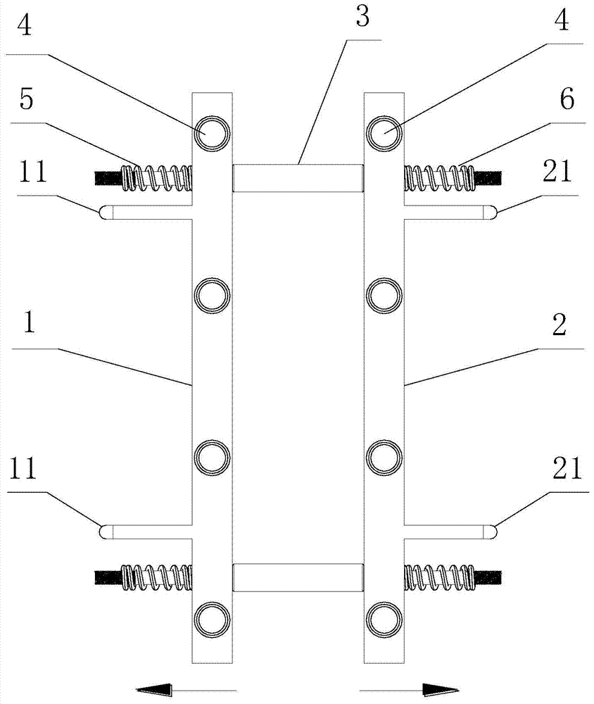
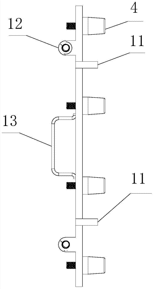
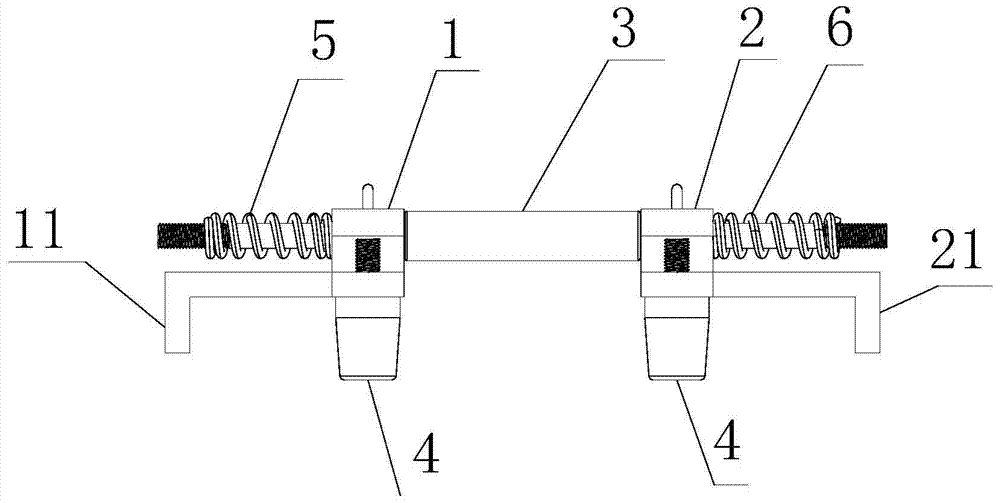
[0022] Such as Figure 1-4 as shown, figure 1 It is a structural schematic diagram of a stripping frame proposed by the present invention; figure 2 A side view of a stripper frame proposed by the present invention; image 3 A top view of a stripping frame proposed by the present invention; Figure 4 It is a schematic diagram of a demoulding frame proposed by the present invention in cooperation with the middle mold.

[0023] refer to Figure 1-3 , a demoulding frame proposed by an embodiment of the present invention, comprising: a first bracket 1, a second bracket 2 and two connecting shafts 3, wherein:

[0024] The two connecting shafts 3 are arranged parallel to each other, and the two connecting shafts 3 include a main body and a first sliding part and a second sliding part located at two ends of the main body; the outer surfaces of the first sliding ...


PUM


Abstract

The invention discloses a novel demolding frame. The novel demolding frame comprises a first support, a second support and connecting shafts, wherein the first support and the second support are connected through the connecting shafts and are arranged in parallel; the extending direction of the first support and the extending direction of the second support are perpendicular to the extending direction of the connecting shafts; the first support and the second support can slide in the extending direction of the connecting shafts; first limiting pins are arranged on the side, away from the second support, of the first support; second limiting pins are arranged on the side, away from the first support, of the second support; the first support and the second support are each provided with a plurality of ejection blocks, the ejection blocks located on the first support are distributed in the extending direction of the first support at intervals, and the ejection blocks located on the second support are distributed in the extending direction of the second support at intervals. According to the novel demolding frame, stress is uniform during demolding, time and labor are saved, the appearance of a product is attractive, and the percent of pass is high; besides, overall demolding is completed at a time, so that the product output per shift is greatly increased.

Description

technical field [0001] The invention relates to the technical field of molds, in particular to a stripping frame. Background technique [0002] When vulcanized products are demolded, different demoulding tools are designed according to different parting structures. In the traditional way of demoulding the middle mold (Haffle structure), the Haffle is first pulled apart by the claws of the equipment, and then the products are ejected one by one manually with the help of demoulding rods or rubber hammers. When demoulding, the force-bearing area is uneven, the inertia is large, and manual force cannot be controlled, which can easily cause product breakage, scratches on the appearance, low pass rate, and damage to the mold. Contents of the invention [0003] Based on the technical problems existing in the above-mentioned background technology, the present invention proposes a stripping frame. [0004] The present invention proposes a stripping frame, comprising: a first brac...

Claims


Application Information

Patent Timeline
Patent Type & Authority Patents(China)
IPC IPC(8): B29C33/44
CPCB29C33/44
Inventor 向以发
Owner ANHUI DFSEAL RUBBER SHOCK ABSORBER TECH CO LTD
Why Eureka
Try Eureka