
Automatic pairing method and device for TPMS

A technology of automatic pairing and control modules, applied in transportation and packaging, tire measurement, instruments, etc., can solve problems such as increasing costs and affecting the speed of vehicles off the assembly line

Inactive Publication Date: 2016-04-20
GUANGDONG COAGENT ELECTRONICS SCI & TECH
View PDF6 Cites 14 Cited by
  • Summary
  • Abstract
  • Description
  • Claims
  • Application Information

AI Technical Summary

Problems solved by technology

[0007] In view of the deficiencies in the prior art, the purpose of the present invention is to provide a TPMS automatic pairing method and device, aiming at solving the problem that in the prior art, the pairing needs to be manually connected to the device and the vehicle body diagnostic interface, which greatly affects the speed of the vehicle off-line , each low-frequency wake-up device contains a lot of components, which increases the cost of defects

Method used


Image

  • Automatic pairing method and device for TPMS
  • Automatic pairing method and device for TPMS
  • Automatic pairing method and device for TPMS

Examples


Embodiment Construction

[0033] In order to make the object, technical solution and effect of the present invention more clear and definite, the present invention will be further described in detail below. It should be understood that the specific embodiments described here are only used to explain the present invention, not to limit the present invention.

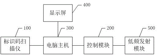
[0034] The present invention provides a structural block diagram of a preferred embodiment of a TPMS automatic pairing device, as figure 1 As shown, the TPMS automatic pairing device includes an identification code scanner 100 for scanning the identification code on the vehicle body, a control module 200 for sending pairing commands, and a host computer for the identification code scanner 100 to communicate with the control module 200 300, a display screen 400 for displaying the pairing result, and a low-frequency transmitting module 500 for triggering the TPMS sensor in the car tire to send tire data;

[0035] Wherein, the host computer 300 is r...


PUM


Abstract

The invention discloses an automatic pairing method and device for a TPMS. The device comprises an identification code scanner for scanning an identification code on a car body, a control module for sending a pairing instruction, a computer host for communicating the identification code scanner with the control module, a display screen for displaying a pairing result and a low-frequency transmitting module for triggering a TPMS sensor in a car tire to send tire data, wherein the computer host is connected with the code scanner, the display screen and the control module, and the control module is also connected with the low-frequency transmitting module. According to the method and device, in a car production line, automatic non-stop pairing can be achieved, the production line efficiency is improved, and the car offline tact is not disrupted; in addition, device configuration is simplified, and the device cost is lowered.

Description

technical field [0001] The invention relates to the field of automobile production, in particular to a TPMS automatic pairing method and device. Background technique [0002] Direct TPMS generally consists of several sensor modules (depending on the number of car tires) and at least one receiving module. Each sensor module has an address ID. Before the system is used, the receiving module needs to use various means to record the location of different wheel positions The sensor module address ID, this process is called pairing. When the system is running, the address ID information in the received signal is used to distinguish whether the signal is sent from the sensor module used by the vehicle, and which wheel position sensor module it is sent from, so as to eliminate signal interference from other vehicles and determine The information represents the specific wheel position, providing consumers with accurate reference information. [0003] In the automotive aftermarket, ...

Claims


Application Information

Patent Timeline
IPC IPC(8): B60C23/04G06K7/00
CPCB60C23/04G06K7/00
Inventor 沈显忠
Owner GUANGDONG COAGENT ELECTRONICS SCI & TECH
Learn More