Tray in dying box

A drying box, storage technology, applied in the direction of preventing mechanical damage to containers, containers, transportation and packaging, etc., to achieve the effect of good physical stability

Inactive Publication Date: 2016-04-20
XINJINWEI NETWORK TECH
View PDF0 Cites 4 Cited by
  • Summary
  • Abstract
  • Description
  • Claims
  • Application Information

AI Technical Summary

Problems solved by technology

The drying box only has the function of ensuring temperature and humidity

Method used


Image

  • Tray in dying box

Examples


Embodiment Construction

[0016] Specific embodiments of the invention will be described in detail below in conjunction with the accompanying drawings.

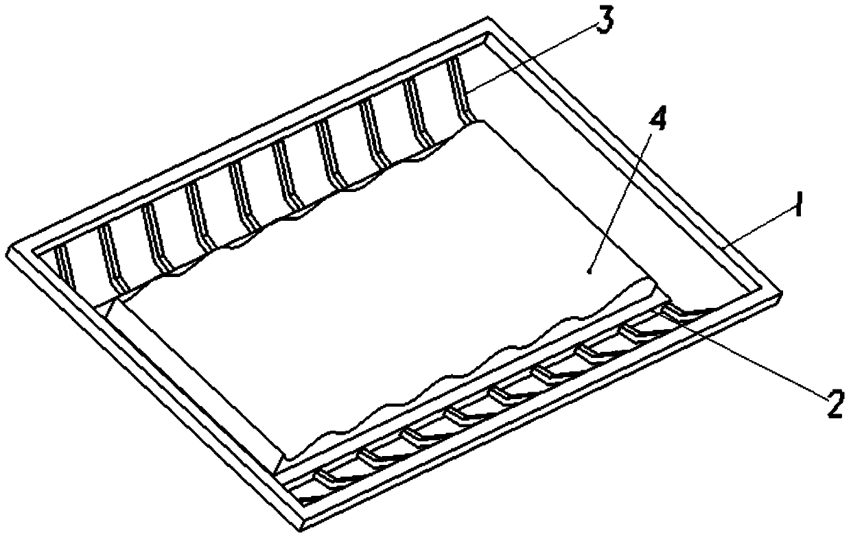
[0017] Such as figure 1 As shown, a tray for a drying box includes a side wall 1 of the box body, a storage plate 2, an L-shaped spring body 3 and a profiling shock-absorbing layer 4;

[0018] Each side length of the storage board 2 is smaller than the side length of the corresponding side wall 1 of the box body, and is connected with the side wall 1 of the box body through a number of evenly distributed L-shaped spring bodies 3 . In this embodiment, the shape of the storage board 2 and the cross-sectional shape of the box side wall 1 are both rectangular.

[0019] The upper surface of the storage board 2 is flat and provided with a profiling shock-absorbing layer 4; the purpose of its setting is to facilitate the placement of various shapes of precision instruments and equipment and experimental materials, and to achieve the purpose of placing them ...


PUM


Abstract

The invention provides a tray in a dying box, which comprises box body side walls, a holding plate, L-shaped spring bodies and a copying shock absorption layer, wherein the edges of the holding plate are shorter than the corresponding edges of the box body side walls, and are connected with the box body side walls through the uniformly distributed L-shaped spring bodies; the upper surface of the holding plate is smooth, and the copying shock absorption layer is arranged on the upper surface of the holding plate; and the L-shaped spring bodies are spiral springs. The tray in the dying box has the advantages and positive effects of having good physical stability on the premise of guaranteeing the temperature and humidity of objects placed on the tray, and keeping precise instrument and equipment and experimental materials placed on the tray safer.

Description

technical field [0001] The invention belongs to the field of drying boxes and related accessories, and in particular relates to a tray for built-in items in a drying box. Background technique [0002] Under normal circumstances, precision instruments and experimental materials that require constant temperature and humidity are placed in the drying box. The drying box only has the function of ensuring temperature and humidity. However, with the improvement of storage requirements, it is becoming more and more important to have a good anti-vibration effect, and ensuring the safety of the equipment and the stability of the experimental materials also plays a particularly important role. Contents of the invention [0003] The problem to be solved by the invention is to provide a tray for the built-in contents of the drying box, which is especially suitable for placing precision instruments and equipment and experimental materials at constant temperature and humidity. It is e...

Claims


Application Information

Patent Timeline
Patent Type & Authority Applications(China)
IPC IPC(8): B65D81/02
Inventor 郝铁乱张永花
Owner XINJINWEI NETWORK TECH
Why Eureka
Try Eureka