A kind of damping foot pad and air conditioner

A foot pad and air conditioner technology, which is applied in the field of vibration reduction, can solve the problems that it is difficult to plug into the installation hole and affect the assembly efficiency of the air conditioner, and achieve the effects of improving transportation reliability, low noise, and easy cooperation

Active Publication Date: 2018-11-13
GREE ELECTRIC APPLIANCES INC +1
View PDF12 Cites 0 Cited by
  • Summary
  • Abstract
  • Description
  • Claims
  • Application Information

AI Technical Summary

Problems solved by technology

Since the outer diameter of the top of the damping foot pad 102 is larger than the diameter of the above-mentioned installation hole, it is difficult to smoothly insert it into the installation hole, which seriously affects the assembly efficiency of the air conditioner.

Method used


Image

  • A kind of damping foot pad and air conditioner
  • A kind of damping foot pad and air conditioner
  • A kind of damping foot pad and air conditioner

Examples


Embodiment 1

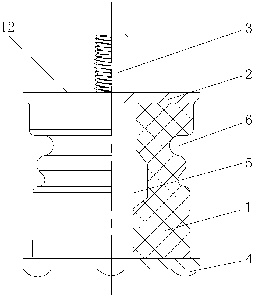
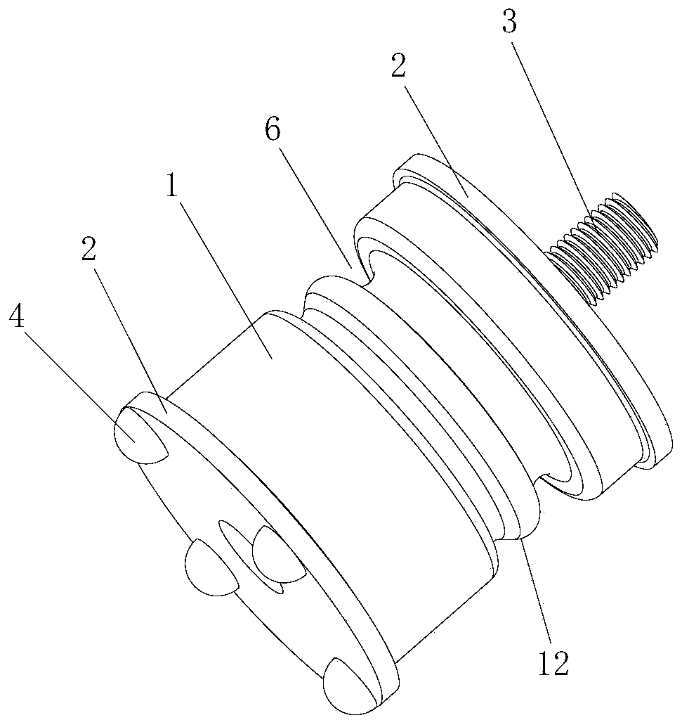
[0035] Such as figure 2 As shown, the present embodiment provides a vibration-damping foot pad 12, including a vibration-damping body 1, which is made of rubber and has a good vibration-damping effect. In order to adapt to different occasions, the vibration-damping foot pad 12 is damped. According to the requirements of vibration performance and limitation of compressor displacement, the shape of the cross section of the vibration damping body 1 is circular, oval or rectangular, so that it has different stiffness characteristics, wherein, when the cross section of the vibration damping body 1 is When the shape is circular, the shock absorber 1 is a cylindrical structure, such as image 3 Shown; when the shape of the damping body 1 cross-section is rectangular, the damping body 1 is a cuboid structure, such as Figure 4 shown.

[0036] The vibration-damping body 1 of this embodiment can be a solid structure, so as to meet the dynamic and static stiffness requirements of the ...

Embodiment 2

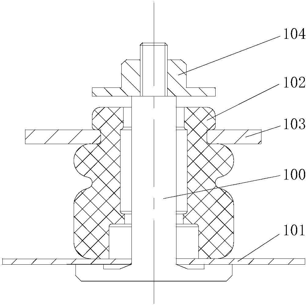
[0045] This embodiment provides an air conditioner, such as Figure 7 or Figure 8As shown, the air conditioner includes a chassis 10 and a compressor 11 installed on the chassis 10, and also includes a vibration-damping foot pad 12 in the preferred embodiment 1, and the vibration-damping foot pad 12 is installed on the mounting plate 111 of the compressor 11 and the chassis 10, the specific installation method has been described in the first preferred embodiment, and will not be repeated here.

[0046] By installing the above-mentioned vibration-damping foot pad 12, after the vibration-damping foot pad 12 is assembled, the vibration of the compressor 11 during operation is transmitted to the vibration-damping body 1 through the mounting plate 111 and the metal plate 2 on the upper end of the vibration-damping foot pad 12, because the rubber inside The friction between the molecules dissipates most of the vibration transmitted by the compressor 11 in the form of heat, so the ...


PUM


Abstract

The invention discloses a vibration reducing foot pad and an air conditioner, and belongs to the technical field of vibration reduction. The vibration reducing foot pad comprises a vibration reduction body and further comprises metal plates fixedly connected to the two ends of the vibration reduction body and a screw rod fixedly arranged on the side, away from the vibration reduction body, of at least one metal plate. The metal plates are fixedly connected to the two ends of the vibration reduction body, at least one metal plate is provided with the screw rod, a locating bolt adopted when an existing vibration reducing foot pad is mounted is omitted, the influence of a fit clearance of the inner hole wall of the vibration reducing foot pad and the locating hole on the vibration reducing effect of the vibration reducing foot pad is eliminated from the source, the vibration reducing effect of the vibration reducing foot pad is better, and the transporting reliability of the air conditioner is higher. Meanwhile, the problem that pipeline reliability in the transporting and carrying process is influenced by the axial clearance of the upper end face of the vibration reducing foot pad and a nut with a gasket when a compressor is actually mounted is solved. A mounting groove structure on the existing vibration reducing foot pad is omitted, matching of the vibration reducing foot pad and a compressor mounting plate is easier, and mounting efficiency is improved.

Description

technical field [0001] The invention relates to the technical field of vibration reduction, in particular to a vibration reduction foot pad and an air conditioner. Background technique [0002] The damping pads mainly play the role of attenuating the transmission of the vibration of the compressor to the chassis of the external unit. At the same time, they also have the functions of bearing and positioning, and can ensure that the pipelines of the external unit of the air conditioner are not damaged during transportation or handling. The rationality of the structure and design parameters of the damping pad directly affects the noise generated by the vibration of the chassis of the air conditioner's external unit, and even affects its reliability during transportation. [0003] In the prior art, the structure and installation form of the damping foot pad are as follows: figure 1 As shown, the positioning bolts 100 are spot-welded on the chassis 101 of the external machine, a...

Claims


Application Information

Patent Timeline
Patent Type & Authority Patents(China)
IPC IPC(8): F16M7/00F16F15/04F24F13/32
CPCF16F15/04F16M7/00F24F13/32
Inventor 张要思张荣婷文智明
Owner GREE ELECTRIC APPLIANCES INC
Why Eureka
Try Eureka