Metal net electromagnetic touch sensor, touch module and electronic touch device

An electromagnetic touch and electromagnetic induction technology, which is applied in the field of touch modules, touch electronic devices, and metal mesh electromagnetic touch sensors, can solve the problem of increasing the number of control circuits or chip I/O interfaces and the inability to better identify touch Control point position information, touch product response speed reduction and other issues, to achieve the effect of reasonable wiring, simple structure, and simplified structure

Active Publication Date: 2016-04-20
江西华创触控科技有限公司
View PDF4 Cites 4 Cited by
  • Summary
  • Abstract
  • Description
  • Claims
  • Application Information

AI Technical Summary

Problems solved by technology

However, the capacitive touch mode, that is, the capacitively coupled touch mode, requires a densely arranged array structure, which requires an array capable of outputting or inputting current signals, thereby increasing the I / O interface of the control circuit or chip. , so that the reaction speed of touch products is reduced, which leads to the inability to better recognize the position information of touch points
If the touch screen of an existing large-sized touch product adopts a capacitive touch mode, the touch product needs to be equipped with a relatively high processor operation to obtain the position information of the touch point, which makes the cost of the touch product very high. high and unresponsive

Method used


Image

  • Metal net electromagnetic touch sensor, touch module and electronic touch device
  • Metal net electromagnetic touch sensor, touch module and electronic touch device
  • Metal net electromagnetic touch sensor, touch module and electronic touch device

Examples


Embodiment 1

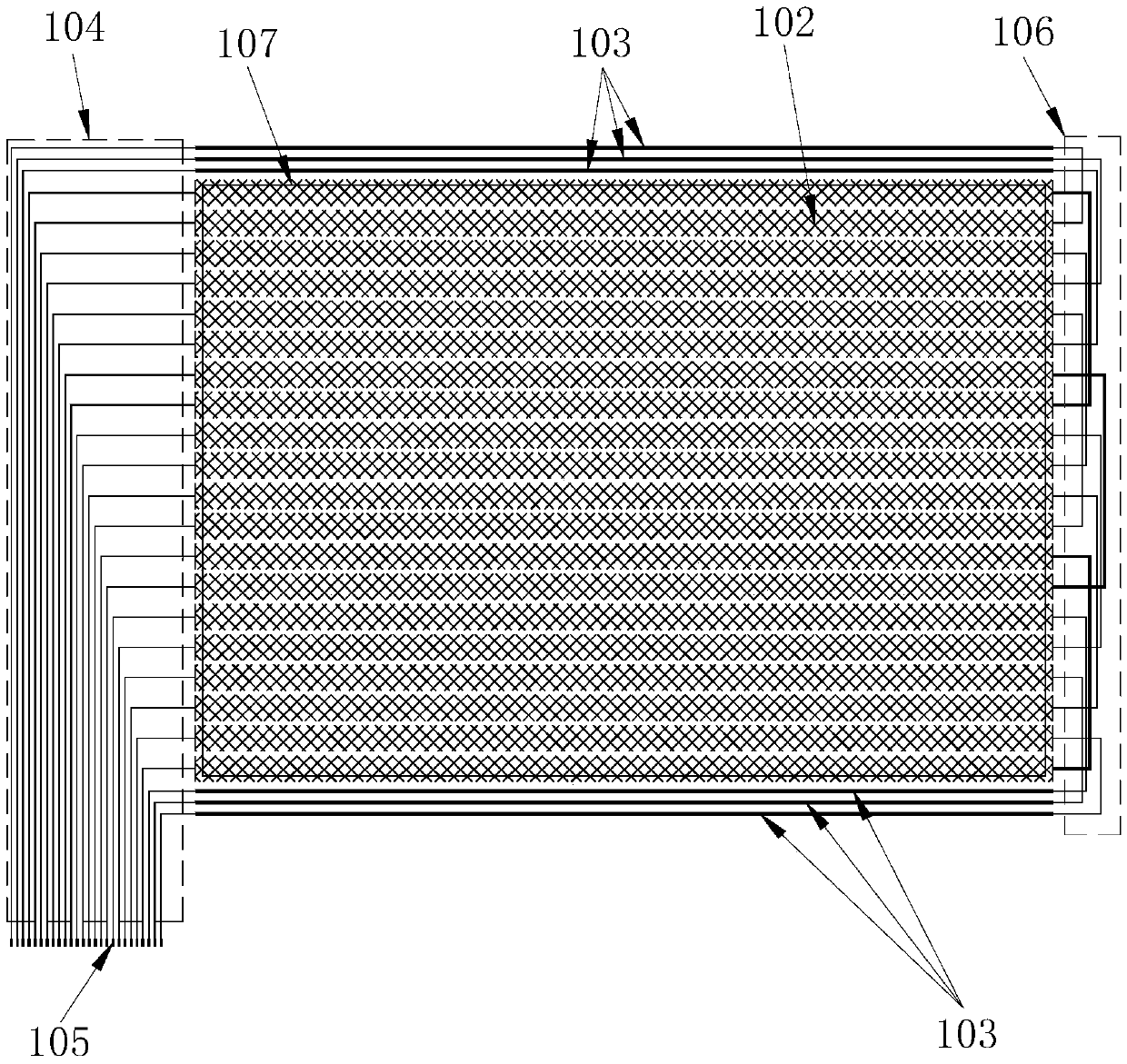
[0059] Such as Figures 1 to 2 As shown: the metal mesh electromagnetic touch sensor provided in Embodiment 1 of the present invention includes a metal mesh electromagnetic induction array, and the metal mesh electromagnetic induction array includes a metal mesh group in a first direction and a metal mesh group in a second direction. There is a first angle greater than 0° between the direction of the mesh group and the direction of the metal mesh group in the second direction, and the metal mesh group in the first direction and the metal mesh group in the second direction are mutually insulated, wherein:

[0060] Such as figure 1 as shown, figure 1 It is shown that the first direction metal mesh group is composed of more than two first direction metal meshes 102 parallel to each other, the left end of the first direction metal mesh 102 is provided with a first signal lead-out line 104, and the first signal lead-out line 104 The end is provided with a first signal lead-out in...

Embodiment 2

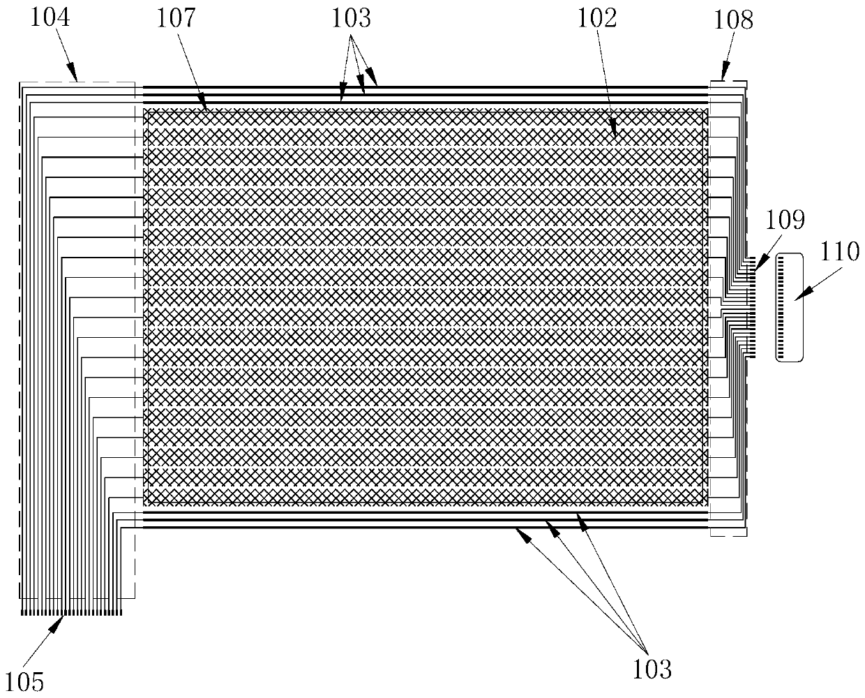
[0067] Such as image 3 and Figure 4 As shown, the metal mesh electromagnetic touch sensor provided in Embodiment 2 of the present invention is different from Embodiment 1 in that: the right end of the first-direction metal mesh 102 in the first-direction metal mesh group in Embodiment 2 That is, the right end is provided with a first wiring 108, and the end of the first wiring 108 is provided with a third signal lead-out interface 109, and the third signal lead-out interface is connected with the first transition film circuit 110; at the same time, the metal mesh electromagnetic induction array Three parallel first solid conductors 103 are arranged horizontally on the outside of the upper end and the lower end of the metal mesh group in the first direction, that is, corresponding to the effective area 107 of the electromagnetic pen touch or corresponding to the visible area 107 of the display screen, and the left end of the first solid conductor is arranged There is a first...

Embodiment 3

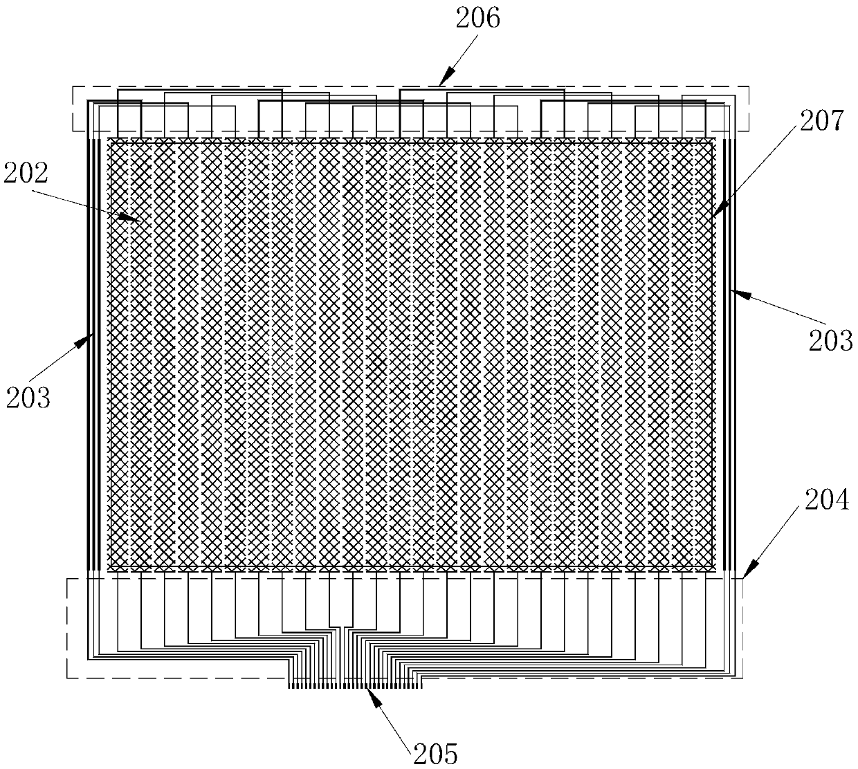
[0071] Such as Figure 5 to Figure 10 As shown, it is the touch module provided by Embodiment 3 of the present invention, wherein, Figure 5 It is a schematic structural diagram of the combination of the metal mesh group in the first direction and the first substrate in the touch module provided by Embodiment 3 of the present invention, Figure 6 It is a schematic structural diagram of the combination of the metal mesh group in the second direction and the second substrate in the touch module provided in Embodiment 3 of the present invention. The touch module provided in Embodiment 3 has a double-layer structure, which includes a first substrate 101 and a The second substrate 201, the first substrate 101 is arranged above the second substrate 201, wherein the first direction metal mesh group in the metal mesh electromagnetic touch sensor is arranged on the upper surface of the first substrate 101, the metal mesh electromagnetic touch sensor The metal mesh group in the second ...


PUM


Abstract

The invention relates to a metal net electromagnetic touch sensor, a touch module and an electronic touch device. The metal net electromagnetic touch sensor comprises an electromagnetic induction array, the electromagnetic induction array comprises a first-direction metal net set and a second-direction metal net set which are insulated mutually, the first-direction metal net set is composed of two or more first-direction metal nets which are mutually parallel, and the second-direction metal net set is composed of two or more second-direction metal nets which are mutually parallel. Extremely fine metal nets which cannot be directly distinguished with the human eyes are adopted as the metal nets forming the electromagnetic touch sensor, the touch module is directly arranged at any position of the surface of a display screen of an electronic device with the display screen, can be arranged at the position between display screen glass and back light and also can be arranged on the back face of the back light of the display screen, and the structural design is convenient and simple, low in cost and convenient to apply and popularize; due to the fact that the electromagnetic touch sensor is made of the metal nets, the resistance is low, the signal to noise ratio is very high, and the electromagnetic touch sensor can be applied and popularized to touch products with the larger size.

Description

technical field [0001] The invention relates to touch technology, in particular to a metal mesh electromagnetic touch sensor, a touch module and a touch electronic device. Background technique [0002] At present, touch products mainly include finger touch products and pen touch products. The touch mode substrates of these touch products are capacitive touch mode and resistive touch mode. Among them, the resistive touch mode is mainly to realize the sensing of the touch points by arranging upper and lower layers of non-contact ITO conductive films in the touch area of ​​the display screen. The main disadvantages are: the upper and lower layers of ITO conductive film are prone to contact failure, which makes the response of resistive touch insensitive, and the resolution of handwriting or pen writing is low. [0003] Compared with the resistive touch mode, the sensitivity of touch products in the capacitive touch mode has been improved to a certain extent. However, the capa...

Claims


Application Information

Patent Timeline
Patent Type & Authority Applications(China)
IPC IPC(8): G06F3/041G06F3/046
CPCG06F3/0412G06F3/046
Inventor 奚邦籽朱德忠
Owner 江西华创触控科技有限公司
Why Eureka
Try Eureka