
Method, device and base station for determining serving base station

A technology for serving base stations and base stations, which is applied in the field of communication and can solve problems such as unreasonable allocation of base stations and system interference.

Active Publication Date: 2019-11-29
NANJING ZHONGXING XIN SOFTWARE CO LTD
View PDF5 Cites 0 Cited by
  • Summary
  • Abstract
  • Description
  • Claims
  • Application Information

AI Technical Summary

Problems solved by technology

[0006] The present invention provides a method, device and base station for determining a serving base station, so as to at least solve the problem in the related art that the allocation of base stations in an ultra-dense network UDN is unreasonable and causes excessive system interference

Method used


Image

  • Method, device and base station for determining serving base station
  • Method, device and base station for determining serving base station
  • Method, device and base station for determining serving base station

Examples


Embodiment approach

[0061] As a preferred embodiment, the edge average path loss value is determined according to the following formula:

[0062] Among them, w k =|C k | / K,

[0063] u represents the penalty factor, which is taken as a constant. For a certain serving small base station k, the relative path loss between all users and the small base station is:

[0064]

[0065]

[0066] Among them, g j (k) is the path loss between the jth user and the kth base station; g j.max Indicates the maximum allowable path loss, calculated by the following formula: g j,max =(P 0 )dBm-(N 0 B)dBm-(F)dB-(SNR jmin )dB, P 0 Indicates the transmit power of the base station, N 0 Represents the noise power spectral density, B represents the channel bandwidth, F represents the received noise figure, SNR jmin Indicates the minimum signal-to-noise ratio threshold at the jth user; C k is the set of users served by small base station k, |C k | is the total number of users served by small base sta...


PUM


Abstract

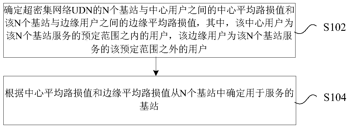
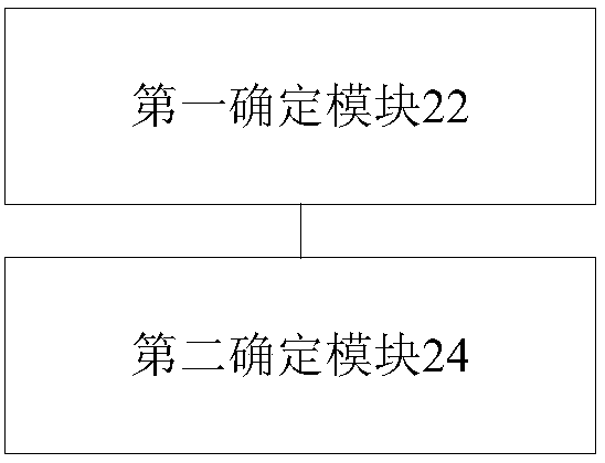
A method, device for determining a serving base station and a base station are disclosed in the present invention, wherein the method comprises: determining a centre average path loss value between the number of N base stations in a Ultra Dense Network (UDN) and a centre user, and an edge average path loss value between the number of N base stations and an edge user, and the centre user being a user in a pre-determined range served by the number of N base stations, and the edge user being a user outside the pre-determined range served by the number of N base stations; and determining a base station for serving from the number of N base stations according to the centre average path loss value and the edge average path loss value. With the present invention, the problem of excessive system interference caused by an irrational allocation of base stations in the Ultra Dense Network (UDN) in the related art is solved, and then the effect that interference between the base stations is reduced and system performance is improved is achieved.

Description

technical field [0001] The present invention relates to the communication field, in particular, to a method, device and base station for determining a serving base station. Background technique [0002] In LTE R12, a Small Cell is introduced, that is, a small cell base station, referred to as a small base station for short. Small Cell is a low-power wireless access node that works in authorized and unlicensed spectrum. Small Cell can be used indoors or outdoors, and can cover an indoor space of 10 meters or a range of 2 kilometers in the wild; in contrast, the coverage of a macro base station can reach several kilometers. Small Cell combines femtocell, picocell, microcell and distributed wireless technology. Small Cell is characterized by dense arrangement and overlapping coverage areas. [0003] As one of the business development requirements of 5G, Ultra Dense Networks (UDN for short) is a network architecture formed by Small Cell through high-density deployment without...

Claims


Application Information

Patent Timeline
Patent Type & Authority Patents(China)
IPC IPC(8): H04W48/20
CPCH04W48/20
Inventor 程翔汪彬李红豆常永宇
Owner NANJING ZHONGXING XIN SOFTWARE CO LTD
Learn More