Transmission method and system of sounding reference signals (SRS)
A technology for measuring reference signals and transmission methods, applied in transmission systems, digital transmission systems, and multiple use of transmission paths, and can solve problems such as large inter-cell SRS interference
- Summary
- Abstract
- Description
- Claims
- Application Information
AI Technical Summary
Problems solved by technology
Method used
Image
Examples
Embodiment 1
[0081] Figure 5 It is a flow chart of the SRS transmission method provided by Embodiment 1 of the present invention. Such as Figure 5 As shown, the SRS transmission method provided in this embodiment includes the following steps:
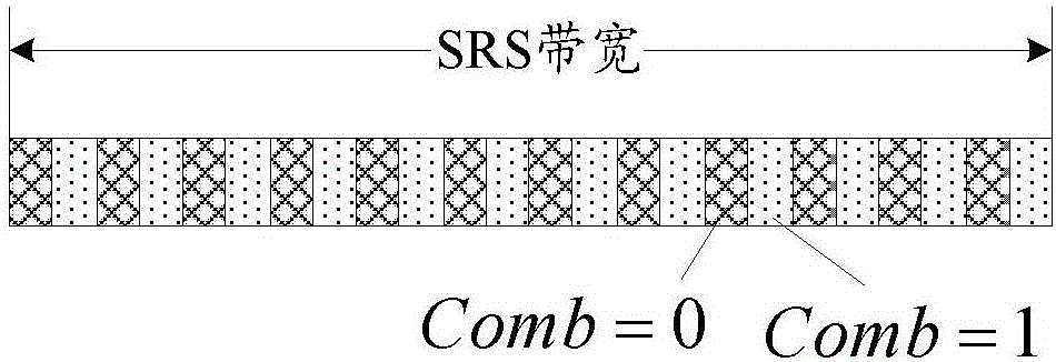
[0082] Step 11: The base station sets the configuration information of the SRS. The SRS configuration information includes: SRS frequency comb hopping enabling configuration information, or SRS frequency comb position randomization enabling configuration information.
[0083] Step 12: the base station sends SRS configuration information to the terminal device.
[0084] After step 11 or step 12, the method further includes: the base station determines a new frequency comb index of the SRS according to the frequency comb index configured by high-layer radio resource control (RRC, Radio Resource Control) signaling and the frequency comb index offset value of the SRS . Wherein, the terminal device sends the SRS sequence at the frequency domain po...
Embodiment 2
[0094] Figure 6 It is a flow chart of the SRS transmission method provided by Embodiment 2 of the present invention. Such as Figure 6 As shown, the SRS transmission method provided in this embodiment includes the following steps:
[0095] Step 21: The terminal device receives the SRS configuration information sent by the base station. The SRS configuration information includes: SRS frequency comb hopping enabling configuration information, or SRS frequency comb position randomization enabling configuration information.
[0096] Step 22: The terminal device processes and transmits the SRS according to the configuration information of the SRS.
[0097] Step 22 includes: the terminal device determines a new frequency comb index of the SRS according to the frequency comb index configured by the high layer RRC signaling and the frequency comb index offset value of the SRS. In addition, the terminal device sends the SRS sequence at the frequency domain position corresponding t...
Embodiment 3
[0107] In this embodiment, the base station receives and measures the SRS signal sent by the terminal equipment, and if the signal to interference plus noise ratio (SINR, Signal to Interference plus Noise Ratio) of the SRS is greater than or equal to a certain threshold value, such as 5dB, the base station It is considered that the SRS signal quality of the terminal device is good enough, and there is no need to configure SRS frequency comb hopping parameters or SRS frequency comb position randomization parameters for the terminal device, or configure SRS frequency comb hopping enabling configuration information or SRS The frequency comb position randomization enable configuration information is disabled; when the quality of the SRS signal received by the base station is less than 5dB, it is considered that the SRS interference of the terminal device is relatively large, and the SRS frequency comb jump enable configuration information can be configured Or the SRS frequency comb...
PUM
 Abstract
Description
Claims
Application Information
 - R&D
- Intellectual Property
- Life Sciences
- Materials
- Tech Scout
- Unparalleled Data Quality
- Higher Quality Content
- 60% Fewer Hallucinations
Browse by: Latest US Patents, China's latest patents, Technical Efficacy Thesaurus, Application Domain, Technology Topic, Popular Technical Reports.
© 2025 PatSnap. All rights reserved.Legal|Privacy policy|Modern Slavery Act Transparency Statement|Sitemap|About US| Contact US: help@patsnap.com


