Yarn cooler

A cooling device and yarn technology, applied in filament/thread forming, textile and papermaking, fiber processing, etc., can solve the problems of fluctuation of cooling air flow, easy generation of eddy current, easy to produce difference in yarn quality, etc., so as to suppress cooling Variation in air flow, suppression of uneven cooling, and effect of uniform quality

Active Publication Date: 2016-04-27
TMT MACHINERY INC
View PDF7 Cites 3 Cited by
  • Summary
  • Abstract
  • Description
  • Claims
  • Application Information

AI Technical Summary

Problems solved by technology

[0004] However, as from Patent Document 1 Figure 4 As can be seen, the air flow of the cooling air around each cooling cylinder varies greatly due to different cooling cylinders
Therefore, there is a concern that the flow rate of the cooling air supplied to the yarn walking space differs greatly among different cooling cylinders
Also, even if only one cooling cylinder is observed, the cooling air flow around it varies greatly in the circumferential direction
Therefore, there is a possibility that the cooling air around the cooling cylinder tends to generate eddies, and the flow rate of the cooling air supplied to one yarn running space may vary greatly in the circumferential direction.
As a result, in the conventional yarn cooling device, due to uneven cooling, there is a problem that the quality of the produced yarn tends to vary.

Method used


Image

  • Yarn cooler
  • Yarn cooler
  • Yarn cooler

Examples


Embodiment Construction

[0028] Embodiments of the yarn cooling device of the present invention will be described below.

[0029] [Melt spinning device]

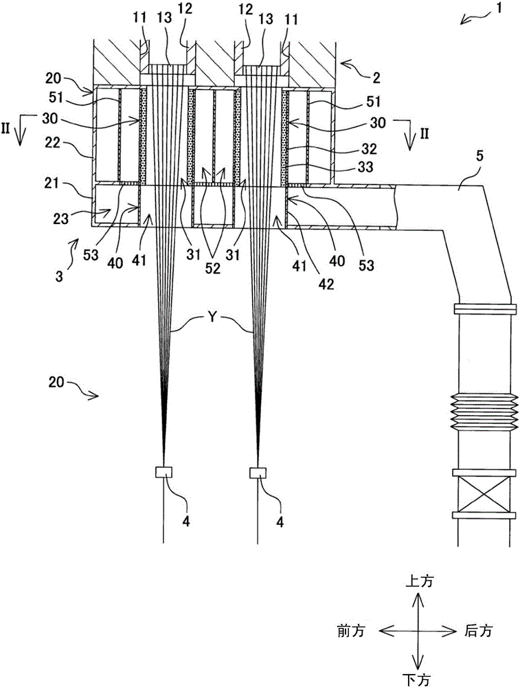
[0030] figure 1 It is a partial sectional view of a melt spinning device equipped with the yarn cooling device of the present invention. like figure 1 As shown, the melt spinning device 1 includes a spinning beam 2, a yarn cooling device 3, an oil feeding device 4, and the like. The spinning beam 2 includes a plurality of unit housings 11 . The spin pack 12 is arranged in each pack case 11, and the melted material that becomes the yarn Y such as molten polyester is stored in the spin pack 12. A spinneret 13 is provided at the lower end of the spinneret 12, and the molten material stored in the spinneret 12 is formed as a plurality of yarns Y from a plurality of through holes not shown in the spinneret 13. Spun out to the bottom. Among them, the plurality of spinnerets 13 are arranged in two rows in a staggered manner along the left and right...


PUM


Abstract

The qualities of yarns are uniformized. For each of cooling cylinders 30, a partition 51 is provided to surround each cooling cylinder 30 and form a circulation space 52 between the partition 51 and the outer circumferential surface of the cooling cylinder 30 to allow cooling wind to circulate in the circulation space 52, and at a border part between a supply space 23 to which the cooling wind is supplied from the outside and the circulation space 52, a flow adjustment plate 53 is provided to circulate the cooling wind from the supply space 23 into the circulation space 52 while adjusting the flow of the cooling wind.

Description

technical field [0001] The present invention relates to a yarn cooling device for cooling yarn spun from a spin beam that spins molten material as yarn from a plurality of spinnerets to below. Background technique [0002] As a yarn cooling device for cooling the yarn spun from the spinning beam, there is a device disclosed in Patent Document 1, for example. In this yarn cooling device, a plurality of cooling cylinders are accommodated in a cooling air supply box, and the yarn is cooled by supplying cooling air to a yarn running space inside the cooling cylinder. Since one cooling air supply box is provided for a plurality of cooling cylinders, the number of ducts for supplying cooling air can be reduced. Therefore, the cooling cylinders can be arranged at a high density, and the production efficiency of the yarn can be improved. [0003] [Patent Document 1] Japanese Unexamined Patent Publication No. 2011-252260 [0004] However, as from Patent Document 1 Figure 4 As can...

Claims


Application Information

Patent Timeline
Patent Type & Authority Applications(China)
IPC IPC(8): D01D5/092
CPCD01D5/088D01D5/092
Inventor 桥本欣三泽田淳川本和弘
Owner TMT MACHINERY INC
Why Eureka
Try Eureka