
A Productivity Prediction Method for Gas Test Wells

A prediction method and productivity prediction technology, applied in prediction, earthwork drilling and production, wellbore/well components, etc., can solve the problem of lack of available information acquisition of optimal reservoirs

Active Publication Date: 2020-01-10
PETROCHINA CO LTD
View PDF5 Cites 0 Cited by
  • Summary
  • Abstract
  • Description
  • Claims
  • Application Information

AI Technical Summary

Problems solved by technology

[0004] The purpose of the present invention is to provide a method for predicting the production capacity of gas test wells, which solves the technical problem that the prior art lacks the acquisition of more available information on preferred reservoirs

Method used


Image

  • A Productivity Prediction Method for Gas Test Wells
  • A Productivity Prediction Method for Gas Test Wells
  • A Productivity Prediction Method for Gas Test Wells

Examples


Embodiment approach

[0045] Specifically, there are at least the following two implementations for the calculation of gas production per meter, which will be described separately below:

Embodiment approach 1

[0046] Embodiment 1: Carry out the calculation of gas production per meter in groups and sections, specifically the following steps in sequence:

[0047] Step 1: Calculate the cumulative permeability curve of each gas test well by using well logging data.

[0048] Step 2: According to the cumulative permeability curve, take the contribution amount greater than the preset percentage as the effective layer thickness of the gas test layer. For example, use the cumulative permeability curve to take the thickness with a contribution greater than 90% as the effective thickness of the test gas layer. Of course, the specific implementation process can also adjust the preset percentage according to actual needs.

[0049] Step 3: Divide the test gas output of the gas test layer by the effective layer thickness of the gas test layer to obtain the gas production per meter of the gas test layer.

[0050] Specifically, the gas test output is specifically the single-layer gas test output or...

Embodiment approach 2

[0058] Embodiment 2: Carry out the calculation of the gas production per meter in groups and sections as follows:

[0059] Step 1: Estimate the effective layer thickness of the gas test layer according to the intersection of neutron density.

[0060] Step 2: Divide the test gas output of the gas test layer by the effective thickness of the layer to obtain the gas production per meter of the gas test layer. In the specific implementation process, the specific implementation process of step 2 in this embodiment can refer to the detailed description of step 3 in the first embodiment.

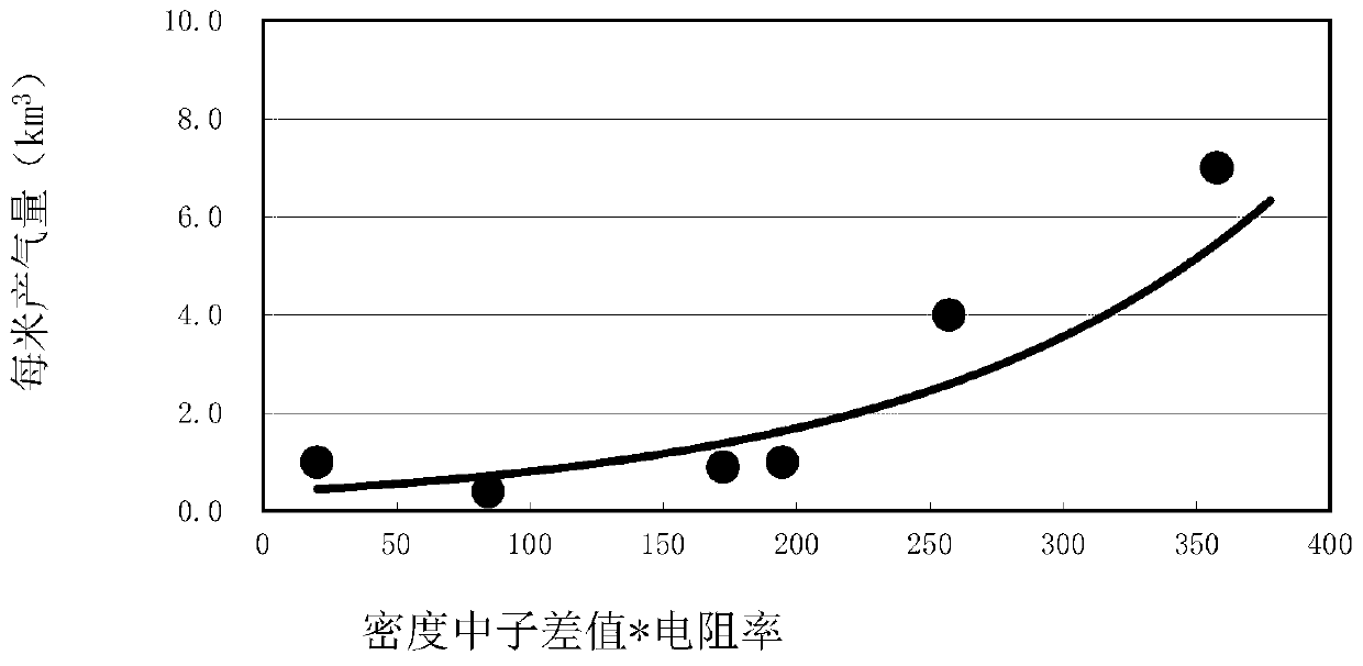
[0061] After the above step S103 is performed, step S105 is then performed: fitting the sensitive parameters of Quanyi 1 and the gas production per meter of the gas test layer to obtain a second productivity equation.

[0062] Specifically, the model reference for fitting the second production capacity equation image 3 Shown, where, y=0.0016x 1.369, R 2 =0.9069, X represents the product of thr...


PUM


Abstract

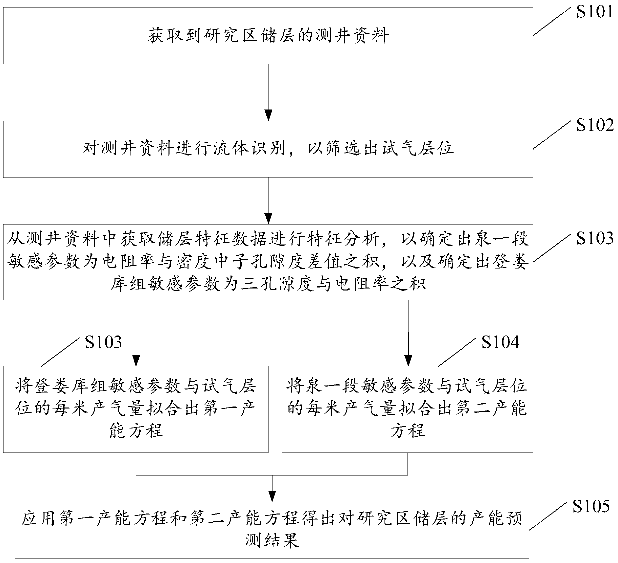
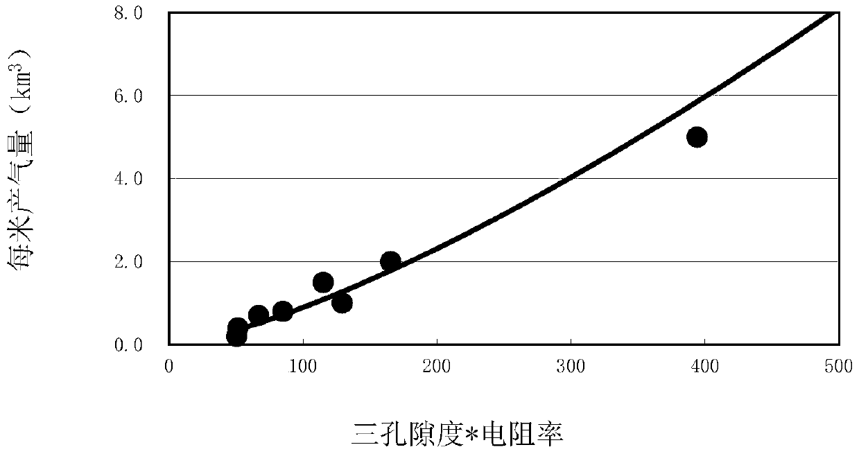
The invention discloses a tested gas well productivity forecasting method, comprising: acquiring logging data of a researched area reservoir; performing fluid identification on the logging data to screen a tested gas position; acquiring reservoir feature data from the logging data and performing feature analysis to determine that a first Quantou formation member sensitive parameter is the product of the resistivity and the density-neutron porosity difference and a Denglouku formation sensitive parameter is the product of three porosities and the resistivity; fitting a first productivity equation based on the Denglouku formation sensitive parameter and every meter of gas production of the tested gas position; fitting a second productivity equation based on the first Quantou formation member sensitive parameter and every meter of gas production of the tested gas position; and applying the first productivity equation and the second productivity equation to obtain a productivity forecasting result of the researched area reservoir, thus solving the technical problems that the reservoir can only be qualitatively optimized and acquisition of more useful information of the optimized reservoir lacks, then realizing fast quantitative forecasting of reservoir productivity, and providing a basis for next optimization of a fracturing position.

Description

technical field [0001] The invention relates to the technical field of oil and gas development, in particular to a method for predicting the productivity of a gas test well. Background technique [0002] Well logging is a method of measuring geophysical parameters using the electrochemical properties, electrical conductivity, acoustic properties, radioactivity and other geophysical properties of rock formations. It belongs to one of the applied geophysical methods (including gravity, magnetism, electricity, seismic and nuclear). During oil drilling, well logging must be carried out after drilling to the designed well depth to obtain various petroleum geology and engineering technical data, which are used as the original data for well completion and development of oil fields, that is, well logging data. [0003] At present, the application of conventional logging data is mainly for reservoir interpretation, which can only qualitatively optimize reservoirs, so it can only qual...

Claims


Application Information

Patent Timeline
Patent Type & Authority Patents(China)
IPC IPC(8): G06Q50/02E21B49/00G06Q10/04
CPCE21B49/00G06Q50/02
Inventor 魏兆胜李忠诚王志文张国一曾凡成张英魁张慧宇宋鹏吕杨周萍
Owner PETROCHINA CO LTD
Learn More