
RF Cavity Device Capable of Automatic Tuning

A cavity and sliding hole technology, applied in the field of RF cavity devices, can solve the problems of short circuit of the first resonator, inability to tune the screw to contact the resonator, etc., and achieve the effect of convenient automatic tuning

Active Publication Date: 2016-04-27
ACE TECH
View PDF2 Cites 6 Cited by
  • Summary
  • Abstract
  • Description
  • Claims
  • Application Information

AI Technical Summary

Problems solved by technology

[0018] When performing automatic tuning according to the existing tuning method, the tuning screw needs to be in contact with the resonator so that the first resonator is short-circuited
However, the specific structure of the RF cavity device cannot make the contact between the tuning screw and the resonator

Method used


Image

  • RF Cavity Device Capable of Automatic Tuning
  • RF Cavity Device Capable of Automatic Tuning
  • RF Cavity Device Capable of Automatic Tuning

Examples


Embodiment Construction

[0045]The present invention can be changed in many ways, and can have various forms. Below, specific embodiments are shown in the drawings and described in detail through the description. However, the intention is not to limit the present invention to the disclosed form, and it should actually be understood to include all changes, equivalents, and substitutes within the scope of the present invention's thought and technology. When describing each drawing, the same reference numerals are attached to the same components.

[0046] Embodiments of the present invention will be specifically described below with reference to the drawings.

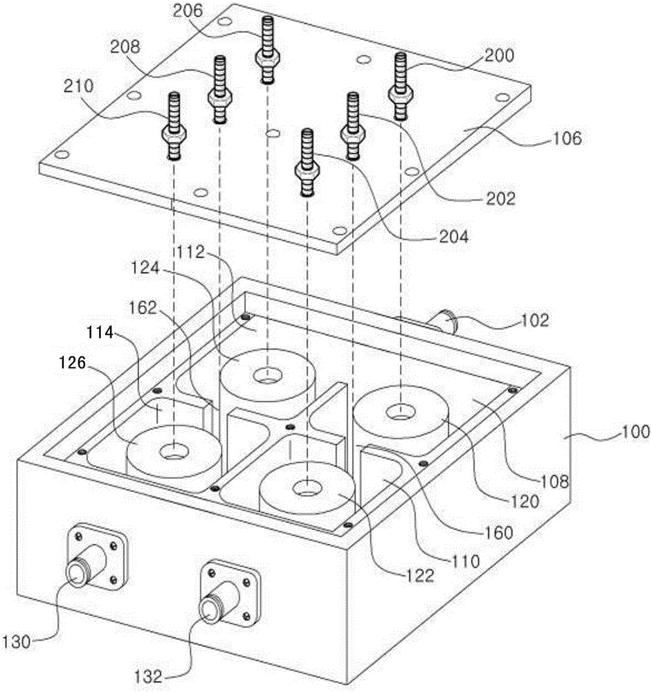
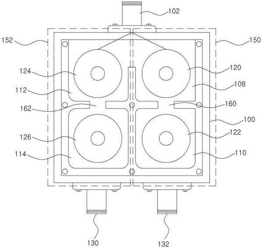
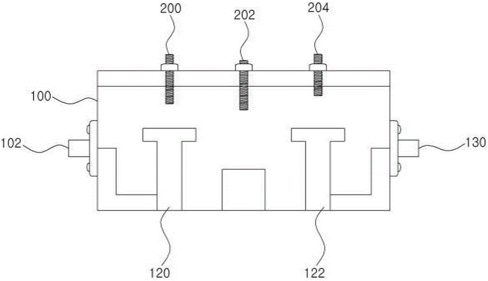
[0047] Figure 4 It is a schematic diagram showing the composition of an automatic tuning device for automatic tuning in an RF cavity device according to an embodiment of the present invention.

[0048] The RF cavity device of the present invention is a device including a plurality of filtering circuits, specifically including a duplexer, a mult...


PUM


Abstract

The invention discloses of an RF cavity device capable of automatic tuning. The device comprises a housing, multiple cavity bodies formed in the interior of the housing, a resonator for storing the cavity bodies and a cover connected to the upper part of the housing. The cavity bodies are arranged to form multiple filtering circuits for independently carrying out filtering. Multiple short-circuit needles are inserted into first cavity bodies respectively connected to input ports of the filtering circuits via the cover. The short-circuit needles are electrically isolated from resonators stored in the first cavity bodies in the first state, and are electrically circuit shorted with the resonators stored in the first cavity bodies in the second state. The device are capable of conveniently automatic tuning via the short-circuit needles.

Description

technical field [0001] Embodiments of the present invention relate to an RF cavity device, and in particular to an automatically tunable RF cavity device. Background technique [0002] With the development of mobile communications, the demand for radio frequency (Radio Frequency, hereinafter referred to as 'RF') cavity devices such as filters, duplexers, and diplexers is also rising sharply. RF devices are used for signal filtering, signal separation and transmission in base stations and other equipment of mobile communication systems, and duplexers are devices used to separate signals with different frequency components. [0003] figure 1 To show an exploded perspective view of the current structure of a biplexer as an RF cavity device, figure 2 A plan view of the diplexer currently used as an RF cavity device. [0004] refer to figure 1 , the current duplexer includes a housing 100 , an input connector 102 , output connectors 130 , 132 , a cover 106 , a plurality of c...

Claims


Application Information

Patent Timeline
IPC IPC(8): H01P1/213
CPCH01P1/20H01P1/20381H01P1/207H01P7/06
Inventor 郑成洙安正学
Owner ACE TECH
Learn More