Fixing device of rear clamp of wing-shaped clamp

A card fixing and clamping technology, applied in the direction of overhead line/cable equipment, etc., can solve the problems of hidden safety hazards, the card cannot be fixed after the airfoil clamp, and it is not easy to install.

Inactive Publication Date: 2016-04-27
STATE GRID FUJIAN ELECTRIC POWER CO LTD +2
View PDF4 Cites 0 Cited by
  • Summary
  • Abstract
  • Description
  • Claims
  • Application Information

AI Technical Summary

Problems solved by technology

In practice, at present, the power supply companies do not use a special fixing device to fix the rear clamp of the airfoil clamp when replacing a single string of tension insulator strings with electricity. In most cases, the following two methods are used to fix the rear clamp of the airfoil clamp. Cards to be fixed: see figure 1 One is to use the nut 101 on the original U-shaped ring 100 bolt on the cross arm to clamp the rear card groove 200, and use the nut 101 on the bolt as the force point for the rear clamp. If the nut is too short, the nut cannot be inserted into the slot of the rear card, and the rear card of the airfoil clamp cannot be fixed; please refer to figure 2 , the other is to thread bolts on the original U-shaped ring 100 on the side of the cross arm, and then clamp the nuts 102 of the bolts into the rear clamping slots 200 of the airfoil fixture for fixing. After the bolt is stressed, it is easy to bend or even break, which has certain safety hazards and is not easy to install

Method used


Image

  • Fixing device of rear clamp of wing-shaped clamp
  • Fixing device of rear clamp of wing-shaped clamp
  • Fixing device of rear clamp of wing-shaped clamp

Examples


Embodiment Construction

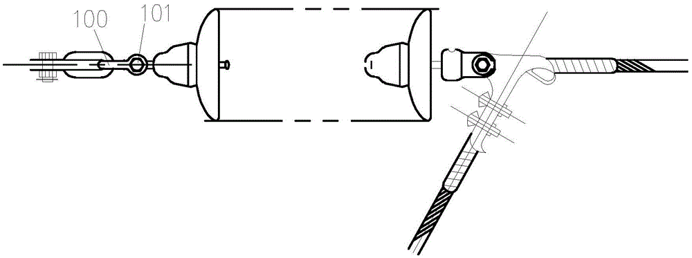
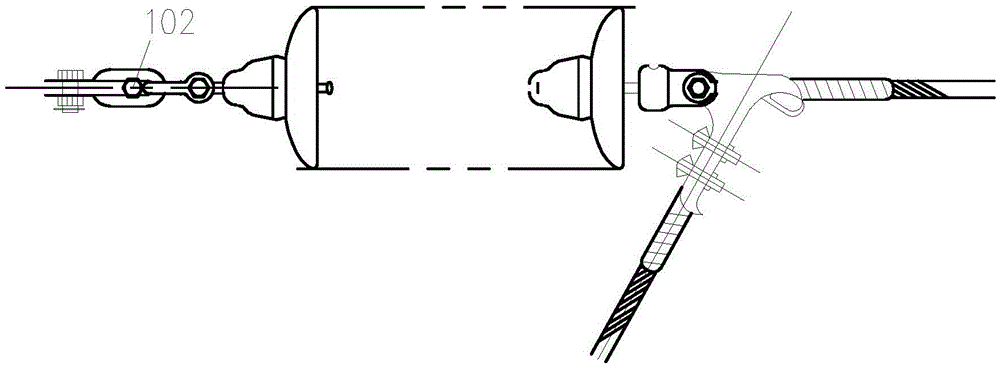
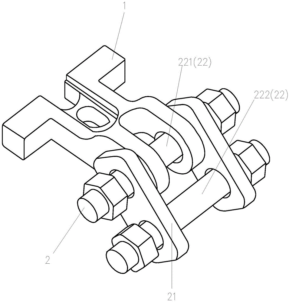
[0014] Please check image 3 , a wing-type clamp rear card holder, which includes a Y-shaped card part 1 and a bridging part 2, and the bridging part 2 includes two parallel and opposite locking plates 21 and two parallel and crossing the two locking plates 21 between the bolts 22, the two bolts 22 are locked to the two locking plates 21 by cooperating with nuts, one end of the Y-shaped clamping part 1 is hinged to the bridging part 2 through a bolt 221, and the other end is used to connect with the wing The card slot 200 of the rear clamp of the type clamp is clamped, and the other bolt 222 of the bridging part 2 is used to connect with the side of the cross arm.

[0015] A U-shaped ring 100 is connected to the side of the cross arm, and the bridging portion 2 is locked to the U-shaped ring 100 through the other bolt 222 .

[0016] When the fixer is installed, one end (sheep head) of the Y-shaped clamping part 1 of the fixer is clamped in the slot 200 of the rear clamp of th...


PUM


Abstract

The invention discloses a fixing device of a rear clamp of a wing-shaped clamp. The fixing device comprises a Y-shaped clamping part and a bridging part, wherein the bridging part comprises two locking plates and two bolts, the two locking plates are oppositely arranged in parallel, and the two bolts cross the two locking plates in parallel and are in locking connection with the two locking plates by matching with nuts; one end of the Y-shaped clamping part is hinged on the bridging part through one of the two bolts, the other end of the Y-shaped clamping part is clamped in a clamping slot of the rear clamp of the wing-shaped clamp, and the other bolt of the bridging part is used for connecting a cross arm side. The fixing device of the rear clamp of the wing-shaped clamp has the advantages that connection between the rear clamp of the wing-shaped clamp and the cross arm side is achieved, the connection is uniform in stress, safe and reliable, and the safety and operation efficiency of hot-line replacement of a single strain insulator string are improved.

Description

technical field [0001] The invention relates to a rear clip holder of an airfoil clip. Background technique [0002] During the live operation of 110kV-220kV line, the replacement of single-string tension insulators of towers usually adopts airfoil clamps. In practice, at present, the power supply companies do not use a special fixing device to fix the rear clamp of the airfoil clamp when replacing a single string of tension insulator strings with electricity. In most cases, the following two methods are used to fix the rear clamp of the airfoil clamp. Cards to be fixed: see figure 1 One is to use the nut 101 on the original U-shaped ring 100 bolt on the cross arm to clamp the rear card groove 200, and use the nut 101 on the bolt as the force point for the rear clamp. If the nut is too short, the nut cannot be inserted into the slot of the rear card, and the rear card of the airfoil clamp cannot be fixed; please refer to figure 2 , the other is to thread bolts on the ori...

Claims


Application Information

Patent Timeline
IPC IPC(8): H02G1/02
CPCH02G1/02
Inventor 陈永平
Owner STATE GRID FUJIAN ELECTRIC POWER CO LTD
Why Eureka
Try Eureka