Component mounting device

A technology for installing devices and components, applied in the direction of measuring devices, electrical components, electrical components, etc., can solve the problems of low productivity and achieve the effect of preventing damage and high position accuracy

Active Publication Date: 2016-04-27
YAMAHA MOTOR CO LTD
View PDF4 Cites 5 Cited by
  • Summary
  • Abstract
  • Description
  • Claims
  • Application Information

AI Technical Summary

Problems solved by technology

However, since each board is inspected, inspection time is required in addition to production time, so there is a problem that productivity is low

Method used


Image

  • Component mounting device
  • Component mounting device
  • Component mounting device

Examples


Embodiment 1

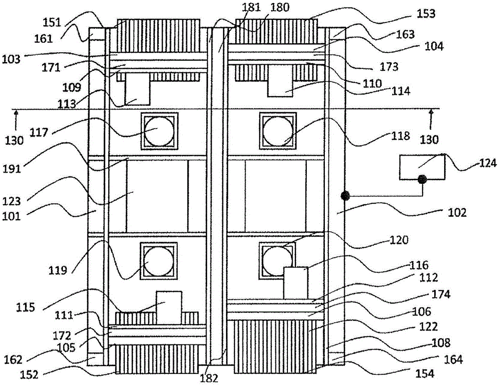
[0029] use Figure 1 to Figure 14 To illustrate Example 1. figure 1 It is a plan view of the entire component mounting device according to Example 1.

[0030] The substrate 123 is conveyed to the electronic component mounting position by the substrate guide 191 from the left side of the drawing sheet.

[0031] A first Y beam 101, a second Y beam 102, and a Y beam guide 180 are provided in a direction orthogonal to the conveying direction of the substrate.

[0032] X beams 103, 104, 105, 106 are provided on the first Y beam 101, the second Y beam 102, and the Y beam guide 180, respectively.

[0033] The X beams 103, 104, 105, 106 are based on actuators 107 such as linear motors installed on the Y beams 101, 102 and Y beam guide 180, respectively, along the guide rails 181, 182 in a direction orthogonal to the conveying direction of the substrate. Move up.

[0034] The X beams 103, 104, 105, and 106 are respectively provided with actuators 109, 110, 111, and 112 such as linear motors.

...


PUM


Abstract

Prior art discloses the feature of measuring the height of the entire substrate for each substrate prior to a production operation for mounting a component on a substrate (component mounting). However, time for inspection was necessary besides production time because each substrate was subjected to inspection, thereby causing productivity to decrease. The present invention has a component mounting unit containing a nozzle and a distance detection unit for optically obtaining the distance between a substrate and a component held by the aforementioned nozzle, and is characterized in that an illumination region formed by the distance detection unit is formed in the vicinity of a section in which the nozzle is projected onto the substrate.

Description

Technical field [0001] The present invention relates to a component mounting device, and relates to, for example, a component mounting device that sucks electronic components and mounts the electronic components on a substrate. Background technique [0002] At present, the work of mounting electronic components on the substrates of various electrical products is automated, and component mounting devices are used at this time. Electronic components are becoming more and more miniaturized. The trend of the component size of electronic components in 2011 was 0.4 (mm) × 0.2 (mm), but it is predicted that the component size that will become the mainstream in 2014 is 0.3 (mm) × 0.15 (mm), so further high speeds are required High-precision installation. [0003] As a conventional technique for preventing damage to electronic components, Patent Document 1 can be cited. Patent Document 1 discloses a technique that detects the warpage of a substrate, which is a major cause of damage to el...

Claims


Application Information

Patent Timeline
Patent Type & Authority Applications(China)
IPC IPC(8): H05K13/04
CPCH05K13/041H05K13/0812G01B11/14H05K13/08
Inventor 高平功井上智博池田裕浅井顺
Owner YAMAHA MOTOR CO LTD
Why Eureka
Try Eureka