Deformable folding structure of multi-rotor type aircraft

A multi-rotor aircraft and folding structure technology, applied in aircraft, unmanned aircraft, rotorcraft, etc., can solve the problems of high power consumption, low mechanical performance, unreasonable folding angle, etc., and achieve a large arm folding angle , Folding structure optimization, good folding effect

Inactive Publication Date: 2016-05-04
GUANGZHOU DINGFEI AEROSPACE TECH CO LTD
View PDF6 Cites 7 Cited by
  • Summary
  • Abstract
  • Description
  • Claims
  • Application Information

AI Technical Summary

Problems solved by technology

However, at present, most multi-rotor aircraft use a fixed-shaped fuselage body. This type of aircraft is bulky, inconvenient to carry, troublesome to disassemble and assemble, and cumbersome to prepare for take-off.
And the rest of the extremely small number of foldable aircraft designs also have shortcomings such as

Method used


Image

  • Deformable folding structure of multi-rotor type aircraft
  • Deformable folding structure of multi-rotor type aircraft
  • Deformable folding structure of multi-rotor type aircraft

Examples


Embodiment Construction

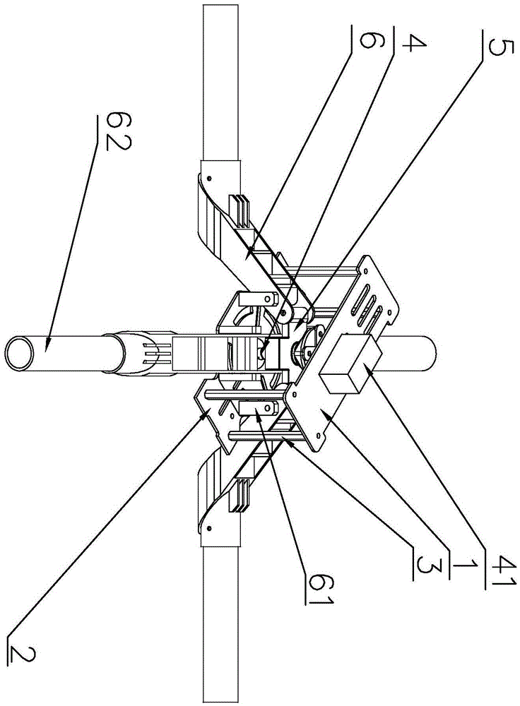
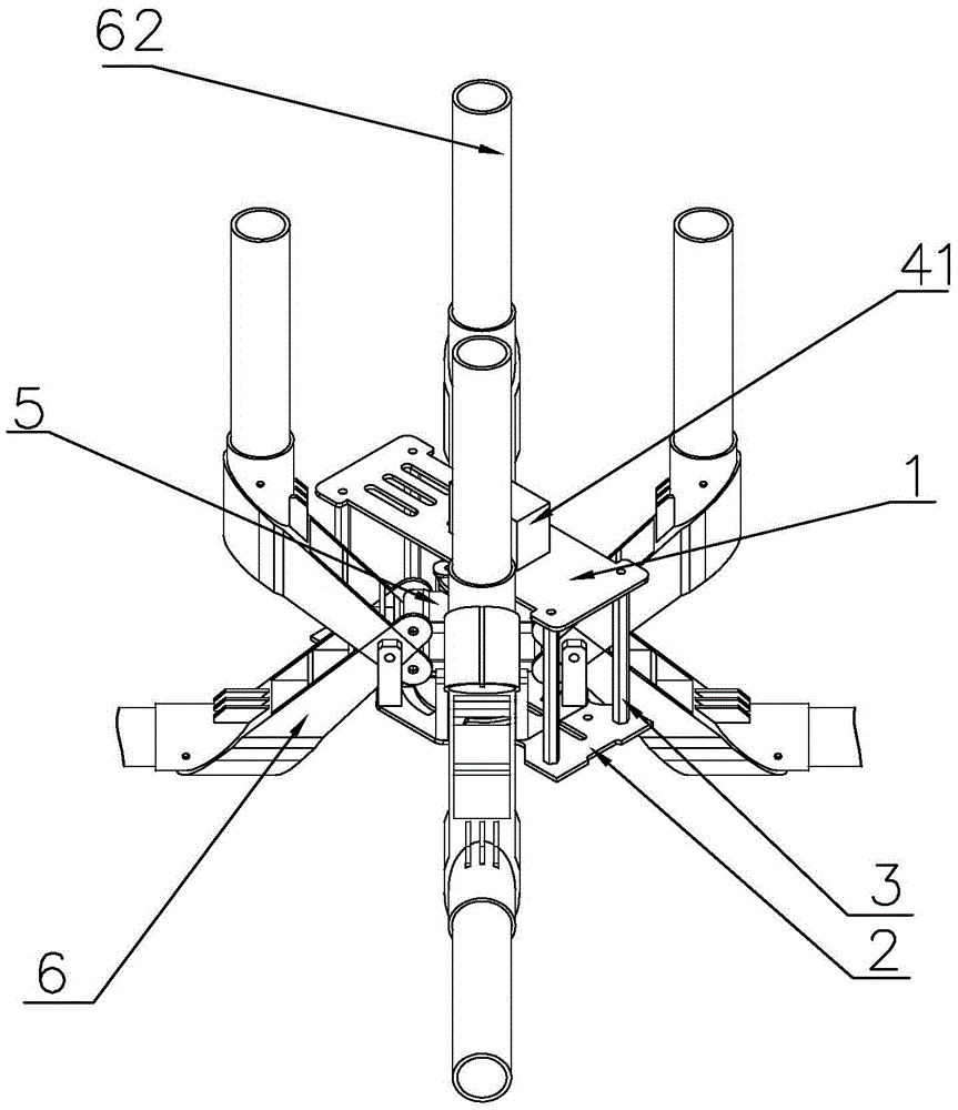
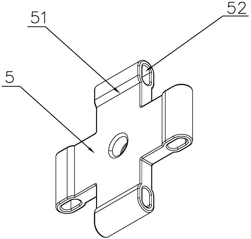
[0016] refer to Figure 1 ~ Figure 3 , the present invention is a deformation and folding structure of a multi-rotor aircraft, comprising an upper carbon plate 1, a lower carbon plate 2 constituting a frame, and a plurality of support rods 3 supported between the upper carbon plate 1 and the lower carbon plate 2, inside the frame There is a lead screw 4 perpendicular to the lower carbon plate 2 and a steering gear 41 that drives the lead screw 4 to rotate. The lead screw 4 is provided with a slider assembly 5, and several machine arms 6 are arranged around the slider assembly 5. The lower carbon plate 2 The upper and lower sides of each machine arm 6 are provided with a fixed support arm 61 perpendicular to the lower carbon plate 2, the top of the fixed support arm 61 is hinged with the machine arm 6, and the slider assembly 5 is provided with several chute 52, each The end of the machine arm 6 is connected with a sliding shaft that can slide horizontally along the chute 52 . ...


PUM


Abstract

The invention discloses a deformable folding structure of a multi-rotor type aircraft, comprising an upper carbon plate, a lower carbon plate and a plurality of support rods, wherein the upper carbon plate and the lower carbon plate form a rack, and the support rods are supported between the upper carbon plate and the lower carbon plate; a lead screw perpendicular to the lower carbon plate and a steering engine for driving the lead screw to rotate are arranged in the rack; a slide block assembly is arranged on the lead screw; a plurality of engine arms are arranged around the slide block assembly; fixed support arms perpendicular to the lower carbon plate are respectively arranged at two sides below each engine arm on the lower carbon plate; the tops of the fixed support arms are articulated with the engine arms; a plurality of chutes are arranged on the slide block assembly; and the end of each engine arm is connected with a slide shaft capable of sliding horizontally along a chute. According to the folding structure, the lead screw connected with the single steering engine rotates to drive the slide block assembly connected with each engine arm to move so as to realize the folding and unfolding of each engine arm; by virtue of the arrangement of the chutes in the slide block assembly, the connection between the engine arms and the slide block assembly can be automatically adjusted according to the running of the slide shafts in the chutes, and a larger engine arm folding angle can be achieved without a multi-link structure; the structure enables the folding structure of the aircraft to be optimized; and because the structure is simplified, a better folding effect can be achieved. The deformable folding structure is applied to the field of aircraft devices.

Description

technical field [0001] The invention relates to the field of aircraft devices, in particular to a deformation and folding structure of a multi-rotor aircraft. Background technique [0002] Multi-rotor aircraft is especially suitable for performing various near-earth environment tasks, such as surveillance, reconnaissance, etc., and has broad military and civilian prospects. However, at present, most multi-rotor aircraft use a fixed-shaped fuselage body. This type of aircraft is bulky, inconvenient to carry, troublesome to disassemble and assemble, and cumbersome to prepare for take-off. However, the rest of the extremely small number of foldable aircraft designs also have shortcomings such as unreasonable folding angles and complicated mechanisms. Most of them are designed using multiple steering gears or multi-stage connecting rod principles. This design has complex structure, low mechanical performance, high power consumption, and heavy weight, which seriously shortens th...

Claims


Application Information

Patent Timeline
IPC IPC(8): B64C27/08
CPCB64C27/08B64U10/10
Inventor 钱伟聪谢佳亮刘建勋
Owner GUANGZHOU DINGFEI AEROSPACE TECH CO LTD
Why Eureka
Try Eureka