
Squeeze roller device

A technology of squeezing rollers and transmission devices, applied in the direction of cells, electrolysis process, circuits, etc., can solve the problems of losing the liquid blocking function, unable to ensure the normal liquid level of the electroplating tank, affecting the effect of synchronous transmission, etc., so as to avoid pulling damage. Effect

Active Publication Date: 2018-05-15
DONGGUAN WERY DOOD CIRCUIT BOARD EQUIP
View PDF6 Cites 0 Cited by
  • Summary
  • Abstract
  • Description
  • Claims
  • Application Information

AI Technical Summary

Problems solved by technology

Among them, the method of improving the surface material of the squeeze roller is to change the squeeze roller to a material with a small squeeze force, so that the circuit board can pass smoothly into the electroplating tank. However, this method makes the squeeze roller lose the liquid blocking function, and the electroplating tank The liquid in the electroplating tank flows out quickly, and the normal liquid level in the electroplating tank cannot be guaranteed; the method of changing the number of teeth of the transmission gear is to reduce or increase the number of teeth of the transmission gear to achieve transmission synchronization, but the disadvantage is that with the extension of use time, it will also Abrasion occurs, which affects the effect of synchronous transmission

Method used


Image

  • Squeeze roller device
  • Squeeze roller device

Examples


Embodiment Construction

[0015] The present invention will be further described below in conjunction with the accompanying drawings and embodiments.

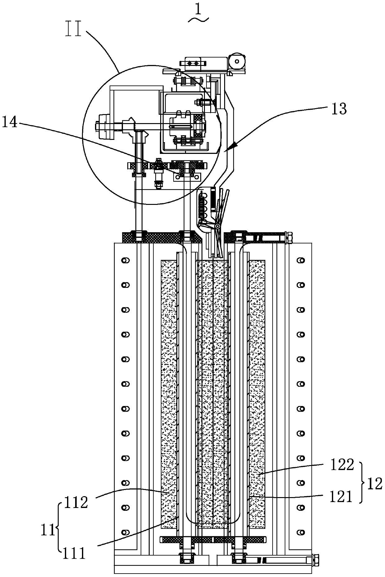
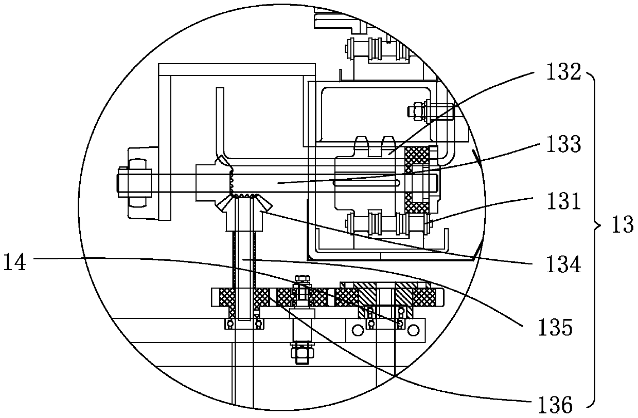
[0016] Please also see figure 1 and figure 2 , wherein, 1 is a schematic structural view of the squeeze roller device of the present invention, figure 2 Yes figure 1 Enlarged view of area II of the squeeze roll arrangement shown. The squeeze roller device 1 includes a first squeeze roller 11 , a second squeeze roller 12 , a transmission device 13 and a one-way bearing 14 . The first squeeze roll 11 and the second squeeze roll 12 are arranged in parallel and juxtaposed.

[0017] The one-way bearing 14 is sheathed on the end of the first squeeze roller 11 and is connected with the transmission device 13. The transmission device 13 drives the first squeeze roller 11 to rotate, and the first squeeze roller 11 rotates. The rotation of a squeeze roller 11 drives the second squeeze roller 12 to rotate relatively.

[0018] The first squeezing roller 11 ...


PUM


Abstract

The invention provides a water extruding roller device. The water extruding roller device comprises a first water extruding roller, a second water extruding roller, a transmission device and a one-way bearing; the first water extruding roller and the second water extruding roller are arranged in parallel; the one-way bearing coats the end part of the first water extruding roller, and is matched and connected with the transmission device; the transmission device drives the first water extruding roller to rotate; and the first water extruding roller rotates to drive the second water extruding roller to relatively rotate. Compared with the prior art, the water extruding roller device, provided by the invention, is additionally provided with the one-way bearing between the first water extruding roller and the transmission device; and when the rotating speed of the first water extruding roller and the second water extruding roller is lower than the conveying speed of circuit boards, the one-way bearing is idle, so that the purpose of no-resistance transmission of the water extruding rollers on the circuit boards is realized, the pull damage of the circuit boards is prevented, and the liquid baffle effect of the water extruding roller device is not influenced.

Description

technical field [0001] The invention relates to the technical field of circuit board processing equipment, in particular to a squeezing roller device. Background technique [0002] In the production line of electroplating equipment, since the entrance and exit of the electroplating copper tank are completely open, the flow of electroplating solution at the entrance and exit is large, so it is necessary to install squeeze rollers at the entrance and exit of the electroplating solution tank to prevent the electroplating solution from leaking out. [0003] In the existing squeeze roller device, the two squeeze rollers are arranged in parallel and juxtaposed, and the transmission gear of the transmission device drives one of the squeeze rollers to rotate, so that the two squeeze rollers rotate relative to each other, and the two squeeze rollers The circuit board is clamped, and the driving device simultaneously drives the transmission gear and the fixture transmission of the cir...

Claims


Application Information

Patent Timeline
Patent Type & Authority Patents(China)
IPC IPC(8): C25D21/00C25D7/12
CPCC25D7/12C25D21/00
Inventor 甘林赵喜华蔡志浩
Owner DONGGUAN WERY DOOD CIRCUIT BOARD EQUIP
Learn More