
Protective circuit of low-voltage equipment continuously working on locomotive

A low-voltage equipment and protection circuit technology, applied in the field of rail transit, can solve the problems of battery voltage monitoring, poor locomotive safety, battery feeding, etc., and achieve the effect of improving safety

Inactive Publication Date: 2016-05-04
ZHUZHOU ELECTRIC LOCOMOTIVE CO
View PDF5 Cites 2 Cited by
  • Summary
  • Abstract
  • Description
  • Claims
  • Application Information

AI Technical Summary

Problems solved by technology

[0002] At present, the low-voltage equipment on locomotives generally draws power from the battery and is controlled by the battery master switch. However, some special low-voltage equipment (such as low-voltage equipment that is continuously working) needs to be in working state all the time and is not controlled by the battery master switch. , need to draw power directly from the battery
[0003] Among them, since the continuously working low-voltage equipment directly draws power from the battery to obtain power, when the continuously working low-voltage equipment fails, the protection circuit of the locomotive’s battery cannot disconnect the failed continuously working low-voltage equipment, resulting in the loss of the locomotive. The entire low-voltage line where the battery and continuously working low-voltage equipment is located is affected, and the safety of locomotive operation is poor
Moreover, the continuously working low-voltage equipment is directly connected to the battery for a long time without monitoring the voltage of the battery, which may easily lead to power feeding of the battery

Method used


Image

  • Protective circuit of low-voltage equipment continuously working on locomotive
  • Protective circuit of low-voltage equipment continuously working on locomotive
  • Protective circuit of low-voltage equipment continuously working on locomotive

Examples


Embodiment 1

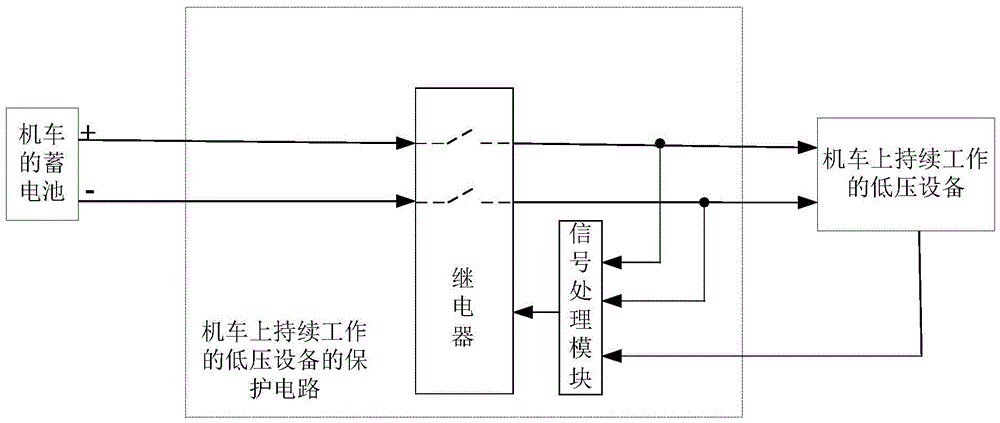
[0030] In this embodiment, a protection circuit for continuously working low-voltage equipment on a locomotive is provided, which is applied to continuously working low-voltage equipment on a locomotive. Please refer to figure 1 , which shows a schematic diagram of the electrical principle of the protection circuit of the continuously working low-voltage equipment on the locomotive provided in the present application. The protection circuit of the continuously working low-voltage equipment on the locomotive includes: a relay and a signal processing module.

[0031] The first end of the relay is connected to the positive pole of the battery of the locomotive, the second end of the relay is connected to the negative pole of the battery of the locomotive, and the third end of the relay is respectively connected to the first input end of the low-voltage equipment continuously working on the locomotive and the signal processing module. The first input terminal is connected, and the ...

Embodiment 2

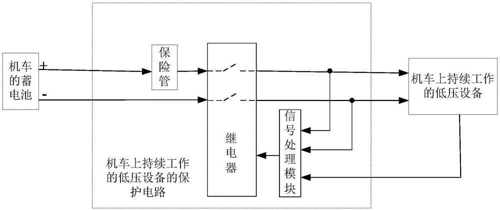
[0039] In this example, in figure 1On the basis of the protection circuit of the continuously working low-voltage equipment on the locomotive shown, another protection circuit of the continuously working low-voltage equipment on the locomotive is extended, please refer to figure 2 ,exist figure 1 On the basis of the protection circuit of the continuously working low-voltage equipment on the locomotive shown, a fuse is also included.

[0040] The first end of the fuse is connected to the positive pole of the battery of the locomotive, and the second end of the fuse is connected to the first end of the relay.

[0041] In this embodiment, after the fuse is added, if the current of the protection circuit of the low-voltage equipment continuously working on the locomotive is large and exceeds the current protection threshold, the fuse will blow to protect other equipment.

Embodiment 3

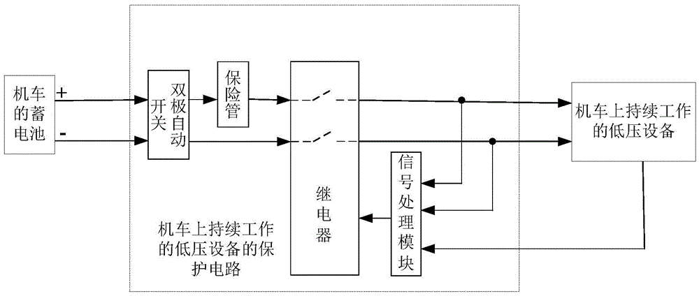
[0043] In this example, in figure 2 On the basis of the protection circuit of the continuously working low-voltage equipment on the locomotive shown, another protection circuit of the continuously working low-voltage equipment on the locomotive is extended, please refer to image 3 ,exist figure 2 On the basis of the protection circuit of the continuously working low-voltage equipment on the locomotive shown, a double-pole automatic switch is also included.

[0044] The first end of the bipolar automatic switch is connected to the positive pole of the battery of the locomotive, the second end of the bipolar automatic switch is connected to the negative pole of the battery of the locomotive, and the third end of the bipolar automatic switch is connected to the first end of the fuse. The fourth terminal of the bipolar automatic switch is connected with the second terminal of the relay.

[0045] In this embodiment, when the current of the protection circuit of the low-voltage...


PUM


Abstract

The invention provides a protective circuit of low-voltage equipment continuously working on a locomotive, wherein the protective circuit is applied to the low-voltage equipment continuously working on the locomotive. The protective circuit of the low-voltage equipment continuously working on the locomotive comprises a relay and a signal processing module; a first end of the relay is connected with a positive pole of an accumulator of the locomotive, a second end of the relay is connected with a negative pole of the accumulator of the locomotive, a third end of the relay is connected with a first input end of the low-voltage equipment continuously working on the locomotive and a first input end of the signal processing module, and a fourth end of the relay is connected with a second input end of the low-voltage equipment continuously working on the locomotive and a second input end of the signal processing module; a third input end of the signal processing module is connected with an output end of the low-voltage equipment continuously working on the locomotive; an output end of the signal processing module is connected with a fifth end of the relay. By means of the protective circuit, the feed phenomenon of the accumulator of the locomotive can be avoided, and operation safety of the locomotive is improved.

Description

technical field [0001] The present application relates to the field of rail transit, in particular to a protection circuit for continuously working low-voltage equipment on a locomotive. Background technique [0002] At present, the low-voltage equipment on the locomotive generally draws power from the battery and is controlled by the battery master switch. However, some special low-voltage equipment (such as low-voltage equipment that is continuously working) needs to be in working state all the time and is not controlled by the battery master switch. , the power supply needs to be drawn directly from the battery. [0003] Among them, since the continuously working low-voltage equipment directly draws power from the battery for power supply, when the continuously working low-voltage equipment fails, the protection circuit of the battery of the locomotive cannot disconnect the failed continuously working low-voltage equipment, resulting in the loss of the locomotive. The en...

Claims


Application Information

Patent Timeline
IPC IPC(8): H02H3/24H02H7/20
CPCH02H3/24H02H7/20
Inventor 李希宁王磊胡亮成本权李辉付利
Owner ZHUZHOU ELECTRIC LOCOMOTIVE CO
Learn More