Supercharge Your Innovation With Domain-Expert AI Agents!

Liquid-receiving unit and rotary electric machine

A technology for rotating electrical machines and liquid storage, which can be used in electromechanical devices, electrical components, electrical components, etc., and can solve problems such as insulation performance degradation and short-circuit accidents.

Inactive Publication Date: 2016-05-04
TOSHIBA MITSUBISHI-ELECTRIC IND SYST CORP
View PDF6 Cites 2 Cited by
  • Summary
  • Abstract
  • Description
  • Claims
  • Application Information

AI Technical Summary

Problems solved by technology

[0003] Here, if the coolant when the coolant leaks in the heat exchanger, or the condensate when the moisture in the cooling gas condenses in the heat exchanger, if the liquid such as the rotor, stator, etc. contact with each other, it may lead to a decrease in insulation performance or a short circuit accident

Method used


Image

  • Liquid-receiving unit and rotary electric machine
  • Liquid-receiving unit and rotary electric machine
  • Liquid-receiving unit and rotary electric machine

Examples


no. 1 approach

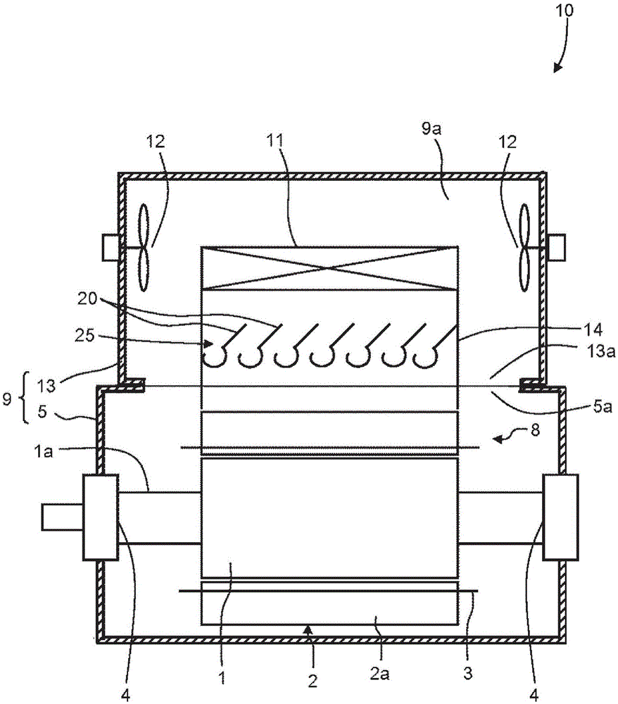
[0021] figure 1 It is a longitudinal sectional view showing the structure of the rotating electric machine according to the first embodiment. The rotary electric machine 10 has a rotor 1 and a stator 2 . A rotating electric machine main body 8 composed of a rotor 1 and a stator 2 is housed in a housing 5 . The rotor 1 is disposed radially around a shaft 1a extending on the axis, and rotates together with the rotation of the shaft 1a. The shaft 1a penetrates the housing 5 at both ends in the axial direction, and is rotatably supported by bearings 4 respectively fixed to both sides of the housing 5 . The stator 2 is disposed on the outer periphery of the rotor 1 at a distance from the rotor 1 in the radial direction. The stator 2 has a stator core 2a and a stator winding 3 wound on the stator core 2a.

[0022] The upper portion of the housing 5 is formed with a housing opening 5a. A cover portion 13 is attached to the upper portion of the housing 5 . A cover opening 13 a f...

no. 2 approach

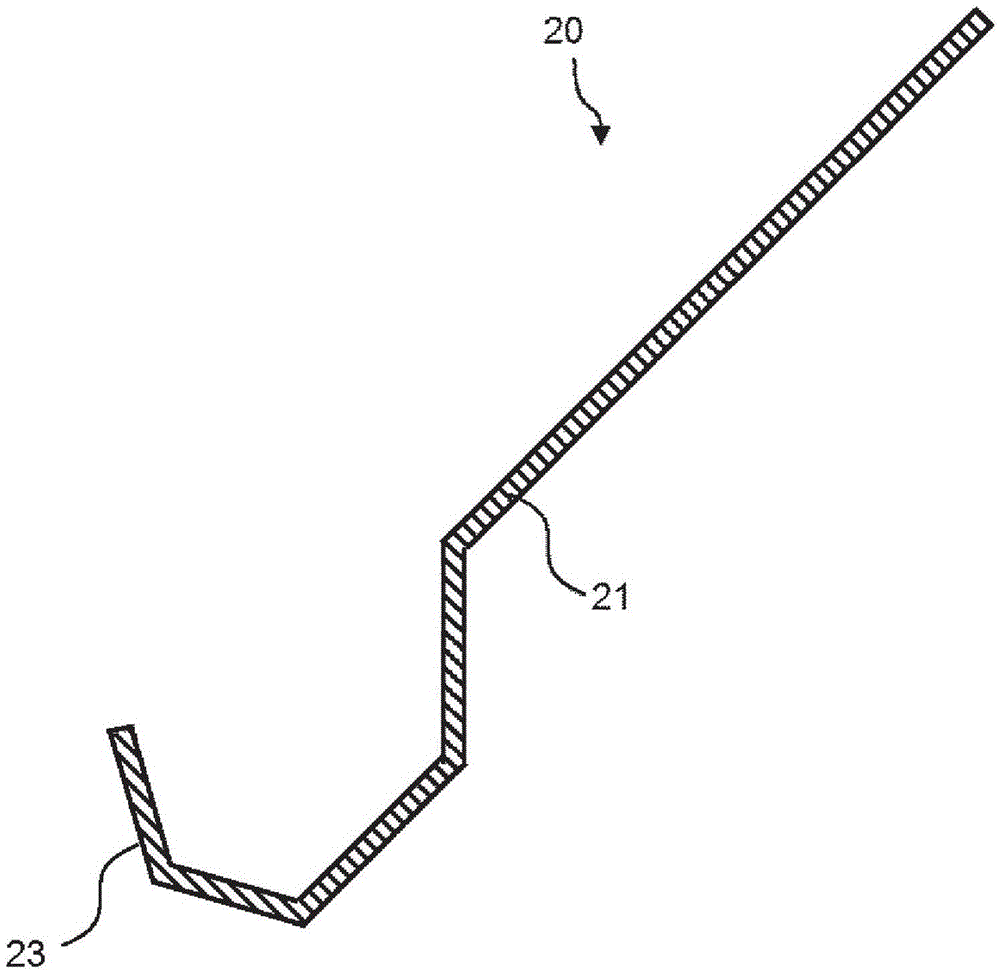
[0038] image 3 It is a transverse cross-sectional view showing a liquid reservoir of the rotating electric machine according to the second embodiment. This embodiment is a modification of the first embodiment. The liquid holding and transferring unit 23 according to the first embodiment is formed to have a rounded curved surface in a direction perpendicular to the longitudinal direction. On the other hand, the liquid holding and transferring portion 23 in the second embodiment is formed to have a plurality of planes connected to each other in a direction perpendicular to the longitudinal direction.

[0039] According to the present embodiment configured as described above, it is possible to reduce the burden of design and manufacture of the liquid reservoir 20 and reduce costs.


PUM


Abstract

This rotary electric machine (10) has: an airtight container (9); a rotary electric machine main body (8) installed in the airtight container; a heat exchanger (11) for cooling a cooling gas inside the airtight container (9); fans (12) for circulating the cooling gas; and a liquid-receiving unit (25). The liquid-receiving unit (25) is installed below the heat exchanger (11) and above the rotary electric machine main body (8) and has multiple liquid receivers (20) that extend in the longitudinal direction and are arranged parallel to each other in the horizontal direction and that receives and transfers liquid from the heat exchanger (11). Each liquid receiver (20) has: a liquid-holding / transferring section that forms a flow path, said flow path being formed so as to be able to hold the liquid, extending in the longitudinal direction, and opening at the top; and a plate-like extension section that is inclined so as to cause the received liquid to flow downward into the liquid-holding / transferring section. An angle formed by the direction of a tangential line of a second side, which is opposite to a first side connecting to the bottom side of the extension section, and an extension line from the extension section is smaller than 90 degrees.

Description

technical field [0001] Embodiments of the present invention relate to a liquid storage unit and a rotating electrical machine using the liquid storage unit. Background technique [0002] In many rotating electric machines, the inside is cooled with gas such as air in order to suppress temperature rise due to heat generation. In a hermetically sealed rotating electric machine, the cooling gas circulates through the casing. In addition, the cooling gas is cooled by the external cooling liquid in the heat exchanger. The coolant is usually water. [0003] Here, if the coolant when the coolant leaks in the heat exchanger, or the condensate when the moisture in the cooling gas condenses in the heat exchanger, if the liquid such as the rotor, stator, etc. If they are in contact with each other, it may lead to a decrease in insulation performance or a short circuit accident. Therefore, as disclosed in Patent Document 1, a liquid storage portion that collects and transfers drippe...

Claims


Application Information

Patent Timeline
Patent Type & Authority Applications(China)
IPC IPC(8): H02K9/19F24F1/36F24F13/22H02K5/10
CPCF24F13/22H02K5/10H02K9/12H02K9/24
Inventor 南洞大辅藤田七荣
Owner TOSHIBA MITSUBISHI-ELECTRIC IND SYST CORP
Features
  • R&D
  • Intellectual Property
  • Life Sciences
  • Materials
  • Tech Scout
  • Unparalleled Data Quality
  • Higher Quality Content
  • 60% Fewer Hallucinations
Learn More