Gripper

A technology of mechanical claws and clamping arms, applied in the field of semiconductor production, can solve problems such as high cost, cumbersome work, and low efficiency

Active Publication Date: 2016-05-11
SHENZHEN DEVOL ADVANCED AUTOMATION CO LTD
View PDF12 Cites 4 Cited by
  • Summary
  • Abstract
  • Description
  • Claims
  • Application Information

AI Technical Summary

Problems solved by technology

This method is costly and inefficient, and it is cumbersome to adjust the clampi

Method used


Image

  • Gripper
  • Gripper
  • Gripper

Examples


Embodiment Construction

[0020] The specific implementation of this patent will be described below in conjunction with the accompanying drawings. It should be noted that this specific implementation is only an example of the preferred technical solution of this patent, and should not be understood as limiting the scope of protection of this patent.

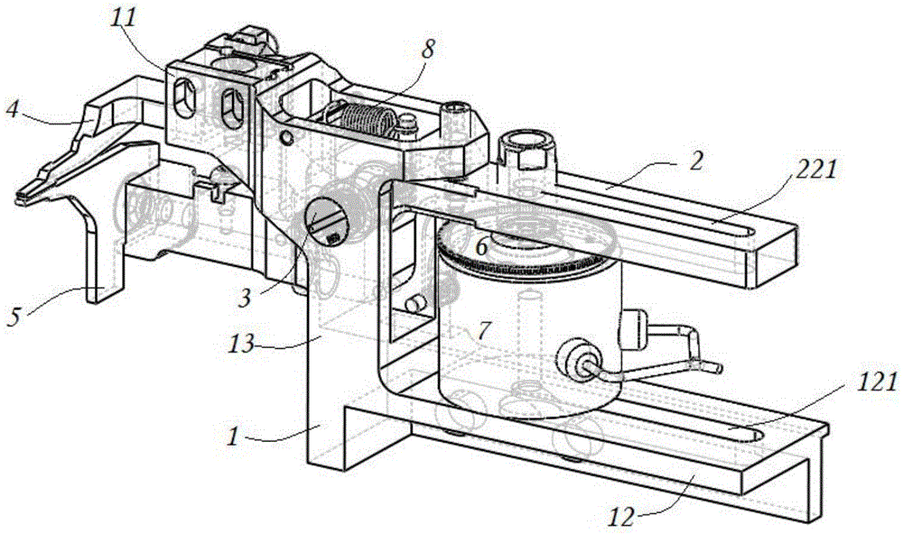
[0021] The overall structure of the mechanical gripper of this embodiment is as follows: figure 1 shown. Place

[0022] The mechanical gripper includes a base 1. The base 1 can be fixedly arranged, and the base is formed in a substantially Z-shape, including two horizontal parts arranged in parallel, that is, a left horizontal part 11 and a right horizontal part 12, and the adjacent ends of the two horizontal parts pass through a vertical The straight part 13 is connected.

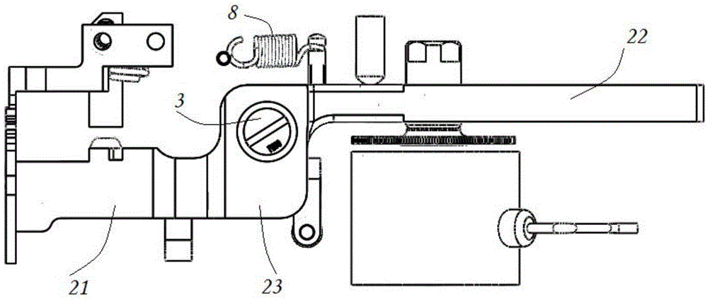
[0023] The gripper also has a clamping arm 2, such as figure 2 As shown, horizontal portions parallel to each other are also formed on the left and right sides of the clamping ar...


PUM


Abstract

The invention discloses a gripper. The gripper comprises a first clamping arm, a second clamping arm, a pivot and a clamping force applying unit, wherein the first clamping arm forms a first lever and comprises a first clamping end and a first force applying end which are positioned on two sides of a fulcrum of the first lever; a first track is arranged on the first force applying end, has a length and is provided with a first end and a second end in the length direction of the first track; the second clamping arm forms a second lever and comprises a second clamping end and a second force applying end which are positioned on two sides of a fulcrum of the second lever; a second track is arranged on the second force applying end, has a length and is provided with a third end and a fourth end in the length direction of the second track; the pivot is used as the fulcrum of the first lever and the second lever; and the clamping force applying unit is arranged on the tracks of the first clamping arm and/or the second clamping arm. Through adjustment of the position of the clamping force applying unit on the tracks, the clamping force of the gripper can be adjusted conveniently and linearly.

Description

technical field [0001] This patent belongs to the field of semiconductor production, and specifically relates to a mechanical claw for linearly adjusting clamping force used in the production of LED wire bonding boards. Background technique [0002] In the production of semiconductor devices, various components, such as wire bonding boards, need to be clamped to facilitate related operations. Usually, clamping various components needs to be done by means of mechanical claws. [0003] However, although the jaws in the prior art are generally able to stably clamp the sheet metal of the wire bonding plate, due to problems such as stress fatigue and the electrical life of the solenoid, the clamping will loosen or even fail after a certain period of use. clamping etc. When clamping looseness occurs, the common technical solution in the prior art is to replace the solenoid with a new one or replace the parts it clamps. This method has high cost and low efficiency, and it is cum...

Claims


Application Information

Patent Timeline
IPC IPC(8): B25B11/00
CPCB25B11/00
Inventor 张振夺舒松赖文杰
Owner SHENZHEN DEVOL ADVANCED AUTOMATION CO LTD
Why Eureka
Try Eureka