

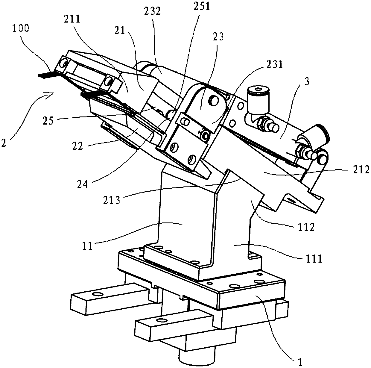
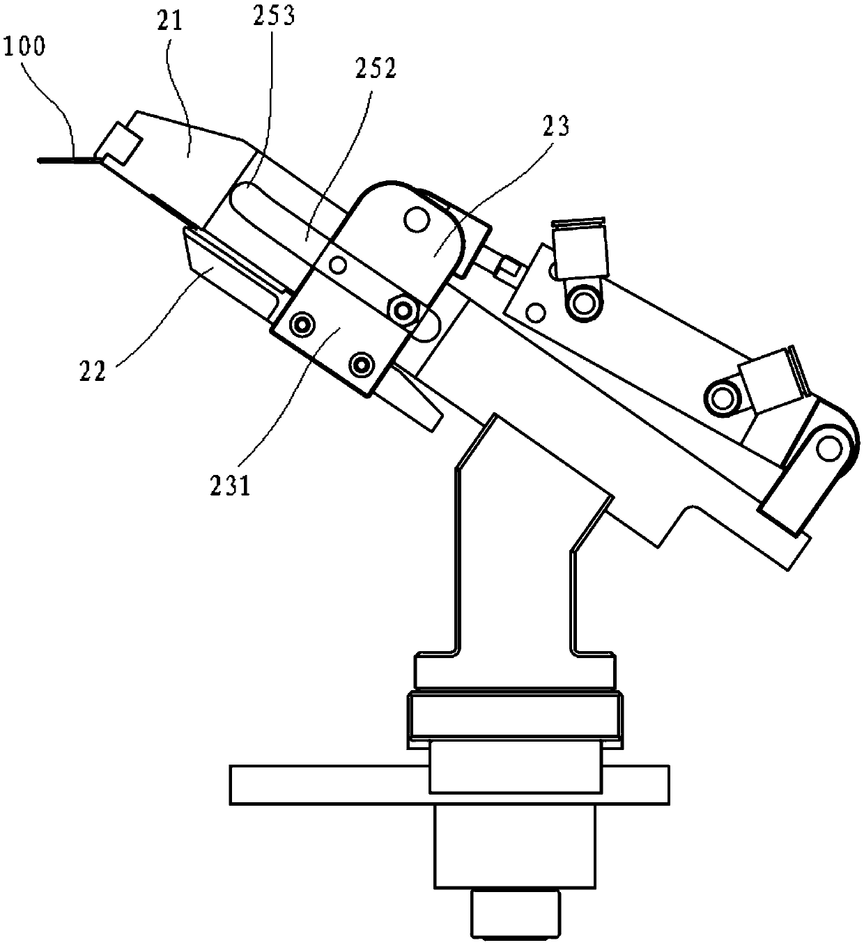
Clamping jaw mechanism
A technology of clamping jaws and fixed jaws, applied in the direction of chucks, manipulators, program-controlled manipulators, etc., can solve the problems of clamping or inserting materials that cannot be bent, and achieve the effect of occupying a small space
- Summary
- Abstract
- Description
- Claims
- Application Information
AI Technical Summary
Problems solved by technology
Method used
Image

Examples
Embodiment Construction
[0036] The technical solutions of the present invention will be clearly and completely described below in conjunction with the accompanying drawings. Apparently, the described embodiments are some of the embodiments of the present invention, but not all of them. Based on the embodiments of the present invention, all other embodiments obtained by persons of ordinary skill in the art without making creative efforts belong to the protection scope of the present invention.
[0037] In the description of the present invention, it should be noted that the orientations or positional relationships indicated by the terms "upper", "lower", "vertical", "horizontal", "inner" and "outer" are based on the The orientation or positional relationship is only for the convenience of describing the present invention and simplifying the description, but does not indicate or imply that the device or element referred to must have a specific orientation, be constructed and operated in a specific orien...
PUM
 Abstract
Description
Claims
Application Information