Gear-changing automatic core-pulling device

An automatic core-pulling and gear-driven technology, applied in the field of core-pulling devices and molds, can solve the problems of not fully automatic production, reduced mold life, low production efficiency, etc., to save manpower and time, and improve production efficiency.

Active Publication Date: 2019-01-01
SHANGHAI JIUTIAN AUTOMOBILE PARTS MFG
View PDF4 Cites 0 Cited by
  • Summary
  • Abstract
  • Description
  • Claims
  • Application Information

AI Technical Summary

Problems solved by technology

like figure 1 As shown, the product 10 has a product body 11 and a protruding structure 12, the protruding structure 12 is arranged obliquely relative to the product body 11, and the protruding structure 12 is provided with a hole 13 along its axial direction (see figure 2 ), if the product 5 needs to be prepared, because the product body 11 is designed with a protruding structure 12, and the inclination angle of the protruding structure 12 is too large, the traditional core-pulling method using a hydraulic cylinder core-pulling will affect the installation of the mold and the molding machine. For the above problems, the manual insert method is generally used
Manual inserts cannot be integrated with the mold in each production, and manual inserts must be knocked out. On the one hand, it cannot achieve fully automatic production when producing products, resulting in the need to waste a lot of manpower and time, and the production efficiency is low; on the other hand, due to Knocking out manual inserts can easily lead to damage to manual inserts, thereby increasing the number of mold repairs and reducing mold life, increasing production costs

Method used


Image

  • Gear-changing automatic core-pulling device
  • Gear-changing automatic core-pulling device
  • Gear-changing automatic core-pulling device

Examples


Embodiment Construction

[0033] In order to understand the technical content of the present invention more clearly, the following examples are given in detail.

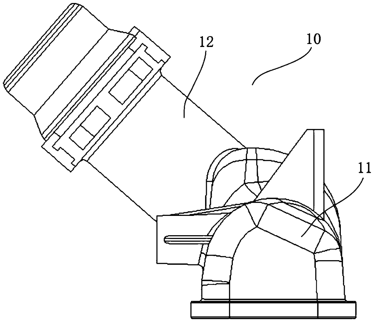
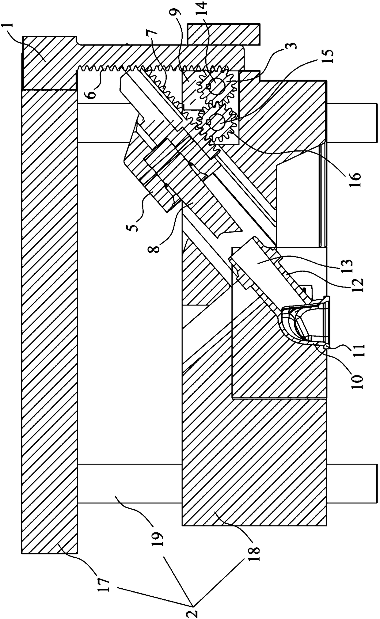
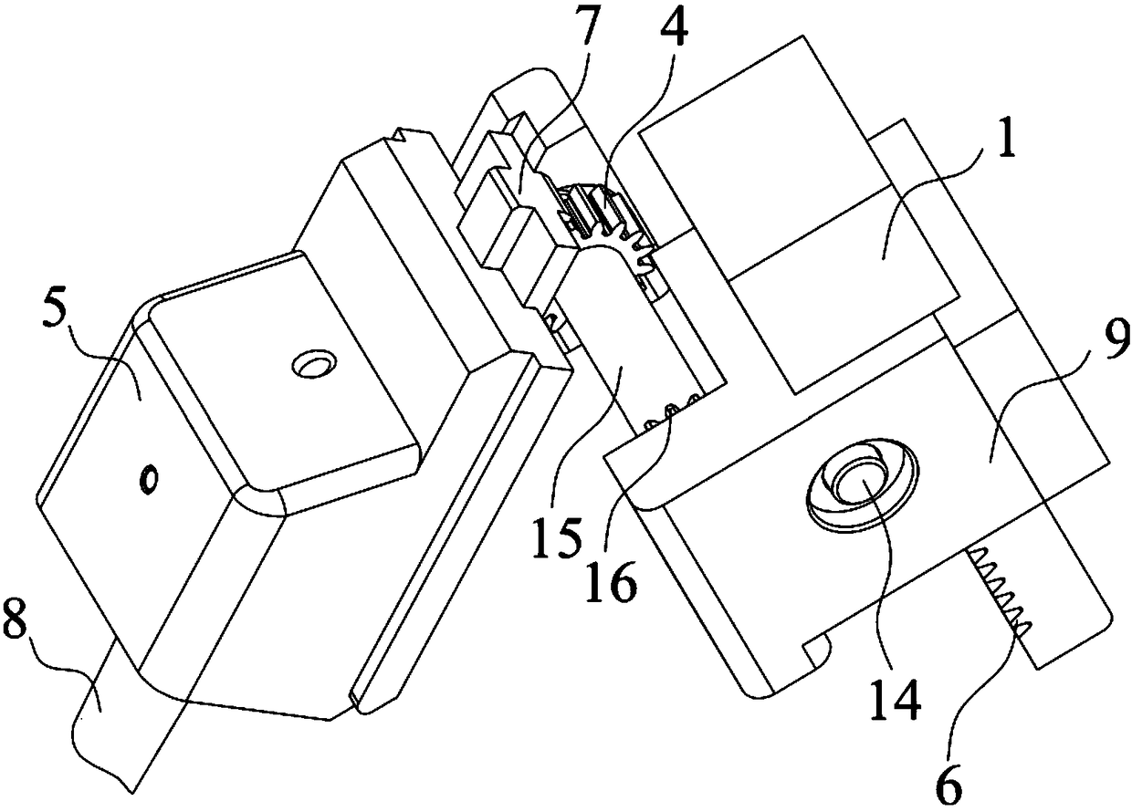
[0034] see figure 2 with image 3 As shown, in a specific embodiment of the present invention, the gear-changing automatic core-pulling device of the present invention includes a gear drive rod 1, a drive component 2, a drive gear 3, a transmission gear 4 and a core-pulling slider 5, and the gear The driving rod 1 is movable up and down, and the gear driving rod 1 is vertically provided with a driving rack 6, and the driving part 2 is connected to the gear driving rod 1 for driving the gear driving rod 1 to move up and down. The driving rack 6 is meshed with the driving gear 3 for driving the driving gear 3 to rotate, the driving gear 3 is connected to the transmission gear 4 for driving the transmission gear 4 to rotate, and the core pulling slider 5 There is a core-pulling rack 7 and a core-pulling component 8 , the core-pulling rack 7 i...


PUM


Abstract

The invention provides a gear turning automatic core pulling device, wherein a gear driving rod is arranged in a vertically moving manner and is provided with a driving rack along a vertical direction, a driving part is connected with the gear driving rod, the driving rack is meshed with a driving gear, the driving gear is connected with a transmission gear and is used for driving the transmission gear to rotate, a core pulling sliding block is provided with a core pulling rack and a core pulling part, the core pulling rack is obliquely arranged and is meshed with the transmission gear, and the core pulling part and the core pulling rack are arranged in parallel. Preferably, the driving part comprises an upper plate and a lower plate which are arranged in an oppositely moving manner along a vertical direction, the upper plate is connected with the upper end of the gear driving rod, and the core pulling sliding block is arranged in the lower plate in a movably way along the inclining direction of the core pulling rack. The gear turning automatic core pulling device can achieve automatic core pulling, save labor and time, improve production efficiency, reduce mold repair times, prolong the service life of the mold, and lower production cost, and is smart in design, simple in structure, and simple and convenient to produce, and cost for development of a mold matched with the device is low, and therefore, the gear turning automatic core pulling device is applicable to large-scale popularization and application.

Description

technical field [0001] The invention relates to the technical field of molds, in particular to the technical field of core-pulling devices, in particular to an automatic core-pulling device for gear direction change. Background technique [0002] In the field of plastic molds, the extended structure of some products forms an included angle with the ejection direction of the main body of the mold. When designing the mold, it is necessary to perform core-pulling in different directions. The core-pulling distance is longer and forms a large angle with the ejection direction. Such as figure 1 As shown, the product 10 has a product body 11 and a protruding structure 12, the protruding structure 12 is arranged obliquely relative to the product body 11, and the protruding structure 12 is provided with a hole 13 along its axial direction (see figure 2 ), if the product 5 needs to be prepared, because the product body 11 is designed with a protruding structure 12, and the inclinati...

Claims


Application Information

Patent Timeline
Patent Type & Authority Patents(China)
IPC IPC(8): B29C45/33
CPCB29C45/332B29C2045/338
Inventor 蔡木华黄志春张亚强
Owner SHANGHAI JIUTIAN AUTOMOBILE PARTS MFG
Why Eureka
Try Eureka