Multifunctional lifting device for vehicle and usage method

A lifting device and multi-functional technology, which is applied in the direction of lifting devices, lifting frames, etc., can solve problems such as lack of driving experience, insufficient road space, and scratching accidents, so as to avoid scratching accidents, reduce road space requirements, and reduce operation difficulty Effect

Pending Publication Date: 2016-05-11
周坤
View PDF0 Cites 17 Cited by
  • Summary
  • Abstract
  • Description
  • Claims
  • Application Information

AI Technical Summary

Problems solved by technology

[0002] The wheel structure of traditional motor vehicles requires a series of complicated operations in the process of parking the motor vehicle in the side position to smoothly park to the designated position. It takes a long time of driving experience for the general driver to complete the correct operation quickly and accurately. The side parking operation; and the newly graduated drivers cannot judge and estimate the safe position of each part of the car during the side parking process due to lack of driving experience, and often cause unnecessary scratches during the side parking operation ACCIDENT
In addition, in the process of U-turn and side parking of motor vehicles, generally enough road space is needed to complete the U-turn or side parking operation, but sometimes the road space is insufficient, and the driver has to make multiple adjustments to complete the U-turn or side parking operation , and sometimes it is impossible for motor vehicles to turn around or park in vacant side parking spaces because of too little road space.

Method used


Image

  • Multifunctional lifting device for vehicle and usage method
  • Multifunctional lifting device for vehicle and usage method
  • Multifunctional lifting device for vehicle and usage method

Examples


Embodiment 1

[0044] Embodiment 1: This embodiment will illustrate how to use the automobile multifunctional lifting device of the present invention to complete the side parking operation of the motor vehicle.

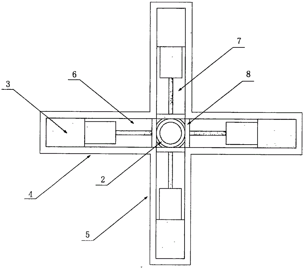
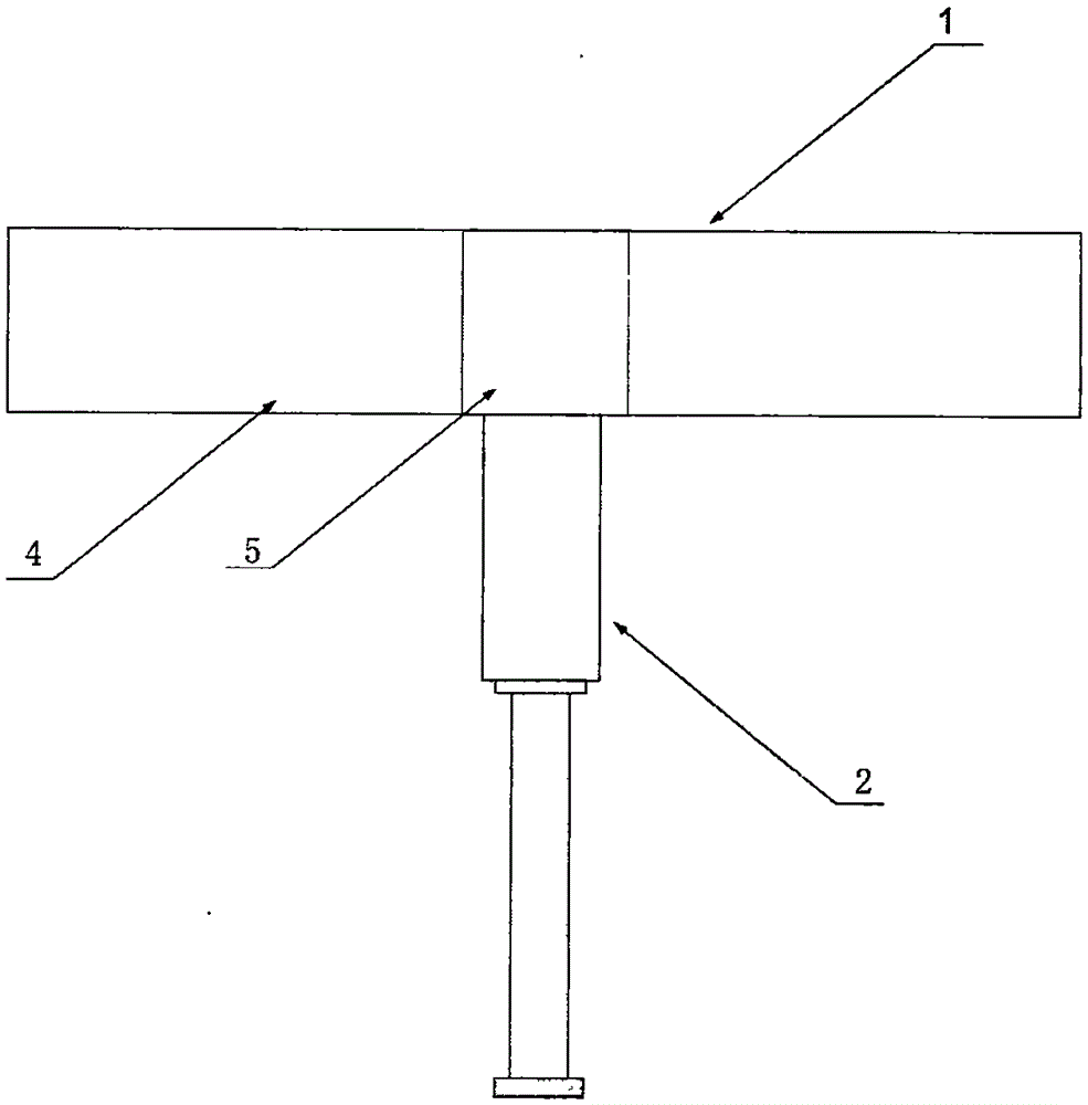
[0045] Depend on figure 1 , figure 2 and Figure 6 As shown, the present embodiment needs 4 automobile multifunctional lifting devices to be respectively installed on the chassis 20 of the motor vehicle in an axisymmetric manner near the positions inside the four wheels, the first rail bracket 1 of each automobile multifunctional lifting device The top of the support arm 4 and the second support arm 5 is installed close to the motor vehicle chassis 20, ensuring that the extension direction of the telescopic cylinder 11 is perpendicular to the motor vehicle chassis 20 and towards the ground. The lengths of the first arm 4 and the second arm 5 of the guide rail bracket 1 used here are equal, while the length of the first guide rail 6 and the second guide rail 7 are equal, and the t...

Embodiment 2

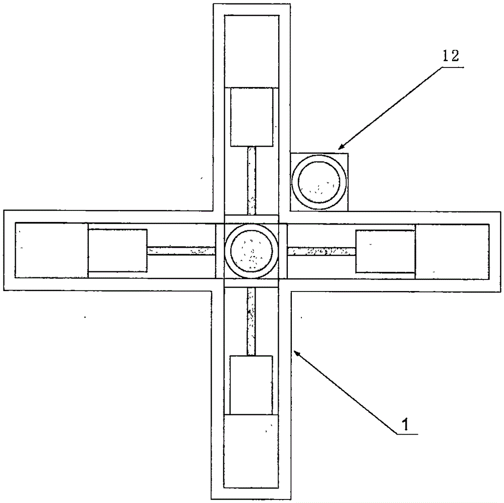
[0047] Embodiment 2: by image 3 , Figure 4 and Figure 6 As shown, in this embodiment, an auxiliary support mechanism 12 is also installed on the guide rail bracket 1. The auxiliary support mechanism 12 mainly includes an auxiliary telescopic cylinder 13 arranged perpendicular to the plane of the support arm, and the piston rod of the auxiliary telescopic cylinder 13 can extend. The maximum length is the same as the maximum length that the piston rod of the telescopic cylinder 11 can stretch out. In this embodiment, the installation method of the multi-function lifting device for automobiles is the same as in Embodiment 1, so that the extension directions of the telescopic cylinder 11 and the auxiliary telescopic cylinder 13 are all perpendicular to the motor vehicle chassis 20 and facing the ground, and in all control processes , the drive cylinder 3, the telescopic cylinder 11 and the auxiliary telescopic cylinder 13 corresponding to the same position in the 4 automobile...

Embodiment 3

[0049] Embodiment 3: by Figure 6 As shown, the present embodiment will explain how the motor vehicle relies on the automobile multifunctional lifting device to complete the motor vehicle U-turn operation with the rear wheel of the motor vehicle as the center of rotation; the installation method of the automobile multifunctional lifting device is the same as in Embodiment 1 in this embodiment Wherein the 2 automobile multifunctional lifting devices installed near the inside position of the front wheel of the motor vehicle are used as the front lifting device, and the 2 automobile multifunctional lifting devices installed near the inside position of the rear wheel of the motor vehicle are used as the rear lifting device. In the example, only the 2 front lifting devices are controlled to participate in the work, and the 2 rear lifting devices are always kept in a stopped state. In the initial state, all the piston rods of the driving cylinders 3 are stretched out and the slider ...


PUM


Abstract

The invention relates to a multifunctional lifting device for a vehicle. The multifunctional lifting device mainly comprises a guide rail support, a support mechanism and driving cylinders, wherein the guide rail support mainly comprises a first support arm and a second support arm, and a first guide rail and a second guide rail are arranged on the first support arm and the second support arm respectively; the support mechanism mainly comprises a sliding block device and a telescopic cylinder, and the sliding block device is arranged in a groove structure of the first guide rail or a groove structure of the second guide rail and can slide in the groove structure in the extension direction of the guide rail; the driving cylinders are fixedly mounted at two ends of the groove structure of the first guide rail and two ends of the groove structure of the second guide rail. With the adoption of the multifunctional lifting device for the vehicle, quick translational motion of the motor vehicle in the lateral direction can be realized, the road space requirement of the motor vehicle during lateral parking is reduced, meanwhile, the operation difficulty of the motor vehicle during lateral parking is reduced, and scratching accidents caused by the motor vehicle during lateral parking are effectively avoided.

Description

technical field [0001] The invention relates to an automobile accessory, in particular to an automobile multifunctional lifting device capable of lifting the automobile body and realizing the horizontal movement of the automobile body and its use method. Background technique [0002] The wheel structure of traditional motor vehicles requires a series of complicated operations in the process of parking the motor vehicle in the side position to smoothly park to the designated position. It takes a long time of driving experience for the general driver to complete a correct operation quickly and accurately. The side parking operation; and the newly graduated driver, due to lack of driving experience, cannot judge and estimate the safe position of each part of the car during the side parking process, and often causes unnecessary scratches during the side parking operation ACCIDENT. In addition, in the process of U-turn and side parking of motor vehicles, generally enough road sp...

Claims


Application Information

Patent Timeline
Patent Type & Authority Applications(China)
IPC IPC(8): B66F7/16B66F7/28
CPCB66F7/16B66F7/28
Inventor 周坤
Owner 周坤
Why Eureka
Try Eureka