A liftable suction cup mechanism for a vacuum cleaner

A technology of a suction cup mechanism and a lifting drive mechanism, which is applied in road cleaning, construction, cleaning methods, etc., can solve problems such as troublesome installation of suction cups, easy damage, waste of manpower and material resources, etc., and achieves avoiding suction cups from being damaged, convenient operation and use, and decentralized The effect of collision force

Active Publication Date: 2018-06-19
HUBEI JULI AUTOMOTIVE TECH CO LTD
View PDF6 Cites 0 Cited by
  • Summary
  • Abstract
  • Description
  • Claims
  • Application Information

AI Technical Summary

Problems solved by technology

[0004] The technical problem to be solved by the present invention is to provide a liftable suction cup mechanism of a dust collection vehicle, which effectively solves the troublesome installation of the suction cup of a conventional sweeping vehicle, and the lifting The structure of the mechanism is relatively complicated, and the operation is more cumbersome when driving. The suction cup of the traditional vacuum cleaner is relatively easy to be damaged when it encounters an obstacle, making the vehicle unable to continue to use, and the replacement of the suction cup requires additional use costs, and the suction cup of the traditional vehicle The structure is mostly fastened on the lifting device, which is inconvenient to disassemble and maintain, and wastes a lot of manpower and material resources

Method used


Image

  • A liftable suction cup mechanism for a vacuum cleaner
  • A liftable suction cup mechanism for a vacuum cleaner
  • A liftable suction cup mechanism for a vacuum cleaner

Examples


Embodiment Construction

[0031] The principles and features of the present invention are described below in conjunction with the accompanying drawings, and the examples given are only used to explain the present invention, and are not intended to limit the scope of the present invention.

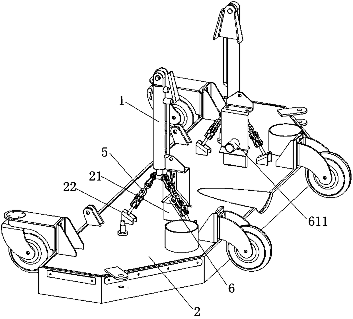
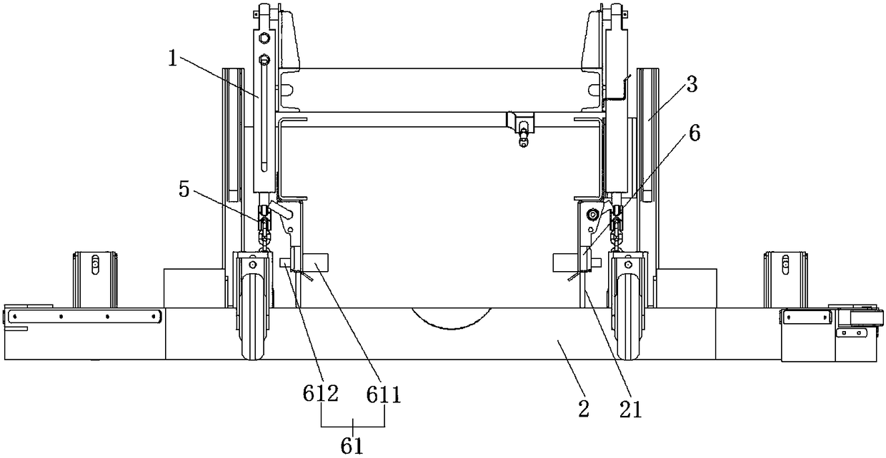
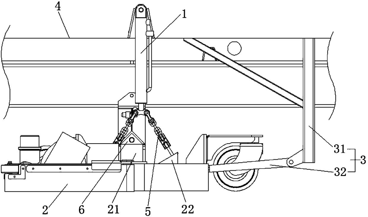
[0032] Example: such as figure 1 , 2 , 3, the liftable suction cup mechanism of the dust collection vehicle of this embodiment includes a lifting drive mechanism 1, a suction cup main body 2 and an auxiliary walking mechanism 3. The lifting drive mechanism 1 is installed on the chassis crossbeam 4, and its driving end is downward. Set, the driving end of the above-mentioned lifting drive mechanism 1 is connected to the above-mentioned suction cup main body 2 through the connecting piece 5, the above-mentioned auxiliary walking mechanism 3 is fixed on the above-mentioned chassis beam 4, and is located at the front side of the above-mentioned suction cup main body 2 along the walking direction, and the above-mentioned...


PUM


Abstract

The invention relates to a structural part of a sanitation truck, in particular to a liftable sucker mechanism of a dust collection vehicle. The liftable sucker mechanism of the dust collection vehicle comprises ascending / descending drive mechanisms, a sucker body and an auxiliary walking mechanism; the ascending / descending drive mechanisms are mounted on a chassis beam, the drive ends of the ascending / descending drive mechanisms are arranged downwards and connected with the sucker body through connection pieces, the auxiliary walking mechanism is fixed to the chassis beam and located on the front side of the sucker body in the walking direction, and the sucker body is connected with the auxiliary walking mechanism. The liftable sucker mechanism of the dust collection vehicle has the advantages that the mechanism is simple in structure and convenient to operate and use, and the sucker device is hung flexibly, so that when the sucker meets a highly protruding obstacle, the collision force can be effectively buffered, collision force is dispersed to a large degree, the situation that the sucker is collided and damaged is avoided, good traction force is achieved, and stability of the sucker in the dust collection process is maintained.

Description

technical field [0001] The invention relates to a structural accessory of a sanitation vehicle, in particular to a liftable sucker mechanism of a dust collection vehicle. Background technique [0002] The vacuum truck has the state of suction and sweeping operation and normal driving state. In the state of suction and sweeping operation, the vehicle is running at a slow speed ≤ 20 km / h, the suction cup is close to the ground, and the distance from the ground is ≤ 10mm, and the suction operation is carried out; in the normal driving state, the vehicle is driving at medium and high speed, and the suction cup is ≥ 250mm from the ground. [0003] The suction cups of conventional washing and sweeping vehicles are mostly fixed and rigidly installed on the front or rear side of the car body. It usually requires a complicated installation structure, and its lifting mechanism structure is relatively complicated, and it is more troublesome to drive up and down. If the suction cup is r...

Claims


Application Information

Patent Timeline
Patent Type & Authority Patents(China)
IPC IPC(8): E01H1/08
CPCE01H1/0827E01H2001/0881
Inventor 徐浩博黄厚福曾萌罗兵
Owner HUBEI JULI AUTOMOTIVE TECH CO LTD
Why Eureka
Try Eureka