Slide member rotation prevention device

A technology of sliding parts and sliding sleeves, which is applied in the direction of linear motion bearings, bearings, shafts and bearings, etc., can solve the problem that the guide hole and the guide pin cannot be closely matched, and achieve the effect of simple structure, reduced processing requirements, and easy processing

Active Publication Date: 2016-05-11
上海阿为特精密机械股份有限公司
View PDF7 Cites 1 Cited by
  • Summary
  • Abstract
  • Description
  • Claims
  • Application Information

AI Technical Summary

Problems solved by technology

[0003] The technical problem solved by the present invention is that the guide holes and guide pins in the prior art cannot be closely matched, and there is a ce

Method used


Image

  • Slide member rotation prevention device
  • Slide member rotation prevention device
  • Slide member rotation prevention device

Examples


Embodiment 1

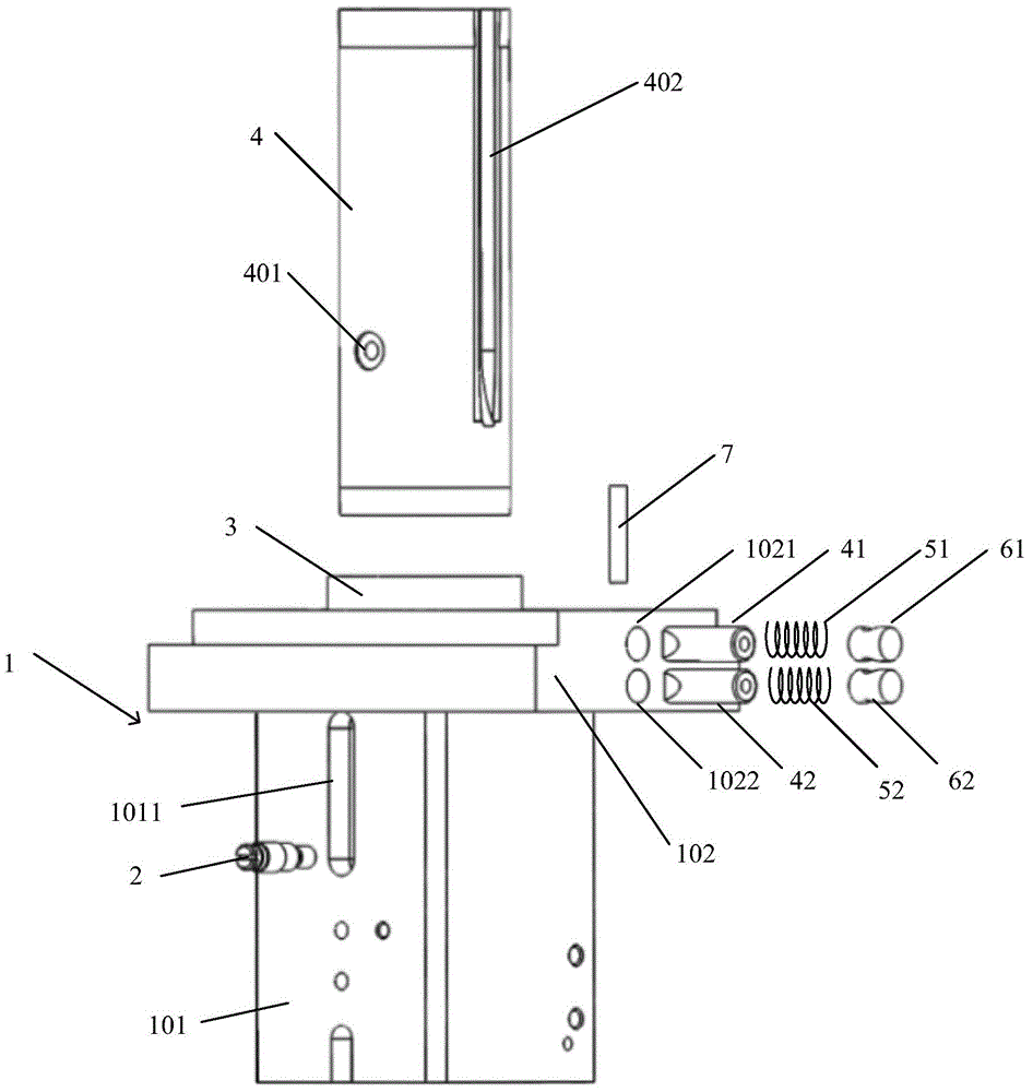
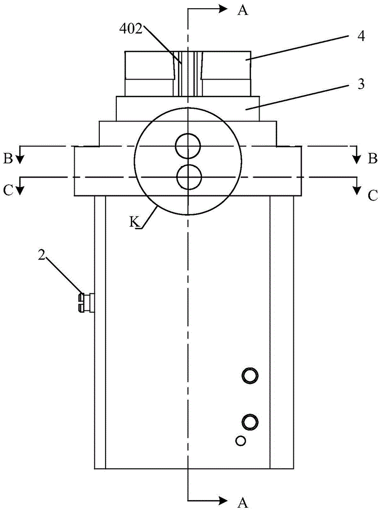
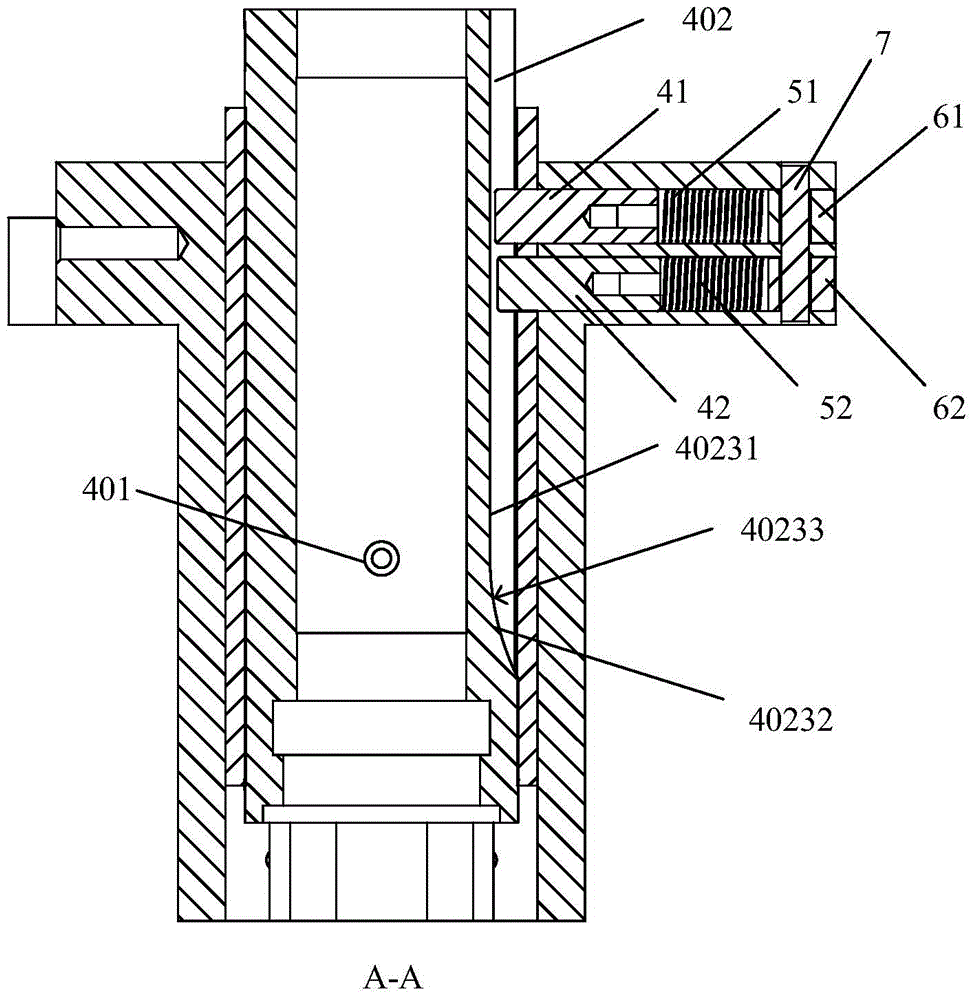
[0029] see figure 1 , a device for preventing a sliding member from rotating includes a main body 1 , a sliding sleeve and a limit screw 2 .

[0030] The sliding sleeve is a steel sleeve 3 shaped as a cylinder, the steel sleeve 3 is placed vertically, and one end of the steel sleeve 3 is fixed inside the main body 1 , and the other end of the steel sleeve 3 is higher than the main body 1 . The sliding part is a cylindrical copper sleeve 4, the copper sleeve 4 is inserted into the steel sleeve 3, and the copper sleeve 4 can slide vertically inside the steel sleeve 3, that is, the copper sleeve 4 4 to be able to slide up and down. A first side 101 of the main body 1 is provided with a waist hole 1011, the straight side of the waist hole 1011 is the same as the sliding direction of the copper sleeve 4 (that is, the straight side of the waist hole 1011 is vertical), and the limit screw 2 Through the waist hole 1011 is fixedly connected with a screw hole 401 formed on the outer w...


PUM


Abstract

The present invention discloses a slide member rotation prevention device comprising a main body for placing a slide member, the slide member is provided with a guide groove, the main body is provided with a first guide round hole and a second guide round hole, the plane of the axle wire of the first guide round hole and the plane of the axle wire of the second guide round hole are not parallel to the sliding direction of the slider member; the slide member rotation prevention device further includes two guide conical-surface pins, the guide conical-surface pins are respectively inserted into the guide groove through the first guide round hole and the second guide round hole, and the guide conical-surface pins are respectively matched with gaps of the first guide round hole and the second guide round hole. The slide member rotation prevention device makes up for the lack of rotation during sliding of a slide member in a main body in the prior art, can effectively control a rotation gap of the slide member in the main body in micron level, meanwhile reduces machining requirements of the guide conical-surface pins and the guide groove, and improves production efficiency. In addition, the device also has the advantages of simple structure, easy processing and the like.

Description

technical field [0001] The invention relates to a device for preventing the rotation of a sliding part, in particular to a high-precision device for preventing the rotation of a sliding part. Background technique [0002] With the increasing number of precision instruments, the demand for precision parts is gradually increasing, especially the demand for precision sliding is particularly huge. Taking a cylindrical sliding part as an example, the sliding part is placed inside a main body, and the sliding part can slide up and down in the vertical direction in the main body. In order to prevent the sliding part from rotating in the main body, the traditional design method It is: setting a guide groove parallel to the sliding direction of the slider on the slider, setting a guide hole on the main body, and inserting a guide pin into the guide groove through the guide hole. This design method can generally prevent the slider from rotating in the main body through the cooperatio...

Claims


Application Information

Patent Timeline
IPC IPC(8): F16C29/02F16C29/12
Inventor 熊朝林李金举
Owner 上海阿为特精密机械股份有限公司
Why Eureka
Try Eureka