
LED lamp

A technology of LED lights and LED light sources, which is applied in the field of LED lighting, can solve the problems of deformation of rotatable LED lights, inaccurate angle positioning, etc., and achieve the effects of improving use order, reducing friction, and avoiding inaccurate angle positioning

Active Publication Date: 2016-05-11
广东比亚迪节能科技有限公司
View PDF5 Cites 0 Cited by
  • Summary
  • Abstract
  • Description
  • Claims
  • Application Information

AI Technical Summary

Problems solved by technology

[0004] The technical problem to be solved by the present invention is to provide an LED lamp for the defect that the existing rotatable LED lamp is deformed due to friction after repeated angle adjustments, which leads to inaccurate angle positioning.

Method used


Image

  • LED lamp
  • LED lamp
  • LED lamp

Examples


Embodiment Construction

[0033] In order to make the technical problems, technical solutions and beneficial effects solved by the present invention clearer, the present invention will be further described in detail below in conjunction with the accompanying drawings and embodiments. It should be understood that the specific embodiments described here are only used to explain the present invention, not to limit the present invention.

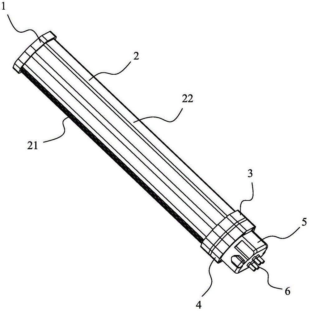
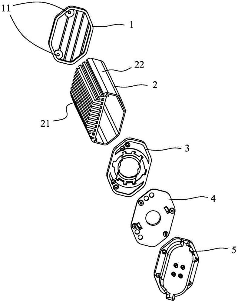
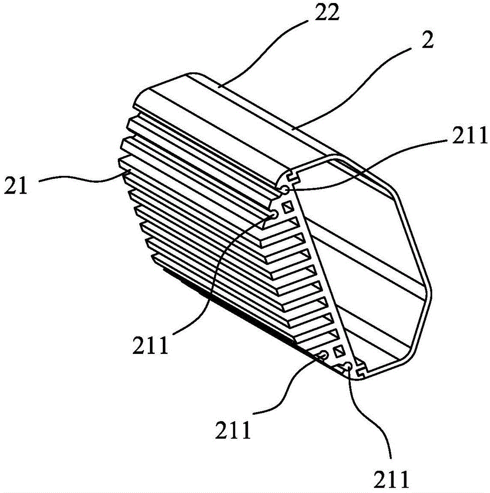
[0034] Such as figure 1 and figure 2 As shown, the LED lamp provided by an embodiment of the present invention includes a first end cover 1, a radiator assembly 2, a rotating member 3, a fixing member 4 and a second end cover 5 arranged in sequence along the length direction of the LED lamp, The first end cover 1, radiator assembly 2 and rotating member 3 are fixedly connected, the fixing member 4 is fixedly connected to the second end cover 5, the rotating member 3 is rotatably connected to the fixing member 4, A lamp cap 6 is arranged on the second end cover 5 .

...


PUM


Abstract

The invention provides an LED lamp. The LED lamp comprises a first end cover, a radiator assembly, a rotating part, a fixed part and a second end cover which are sequentially arranged in the length direction of the LED lamp. The second end cover is provided with a lamp holder. A through hole is formed in the middle of the rotating part. At least one elastic clamping position is formed on the edge of the through hole. Receding holes are formed in the outer sides of the elastic clamping positions correspondingly. A cylindrical structure is arranged on the side, close to the rotating part, of the fixed part. A plurality of gear grooves are formed in the peripheral surface of the cylindrical structure at intervals. The cylindrical structure is inserted into the through hole of the rotating part in a connected mode. According to the LED lamp, the fraction between the rotating part and the fixed part can be reduced, and the problem that the angle location is not precise after the LED lamp is used repeatedly is solved.

Description

technical field [0001] The invention belongs to the technical field of LED lighting, in particular to an LED lamp. Background technique [0002] Existing rotatable LED lamps obtain a certain angle simply by pressing a certain protruding point of the rotating part against the surface of the fixing part. Its principle is to use the friction between the protruding point of the rotating part and the surface of the fixed part to realize angle control and positioning. Usually, the rotation angle range of the rotatable LED lamp of the above structure type is only 0-90 degrees. [0003] Since the existing rotatable LED lamps only achieve angle control and positioning through friction, when the product is repeatedly adjusted for angles, the protrusions of the rotating part or the surface of the fixing part will be deformed due to friction, so that the friction coefficient of the two will gradually decrease, resulting in inaccurate positioning of the angle. Contents of the inventi...

Claims


Application Information

Patent Timeline
Patent Type & Authority Applications(China)
IPC IPC(8): F21S2/00F21V19/02F21V17/16F21Y101/02
Inventor 龙飞虹
Owner 广东比亚迪节能科技有限公司
Learn More