Light source and laser projection apparatus

A light source and laser technology, applied in the field of projection display, can solve the problems of many parts, large volume, complex light source structure, etc., and achieve the effect of facilitating light source structure, light source volume compression, and miniaturization

Active Publication Date: 2016-05-11
HISENSE
View PDF8 Cites 18 Cited by
  • Summary
  • Abstract
  • Description
  • Claims
  • Application Information

AI Technical Summary

Problems solved by technology

This makes the structure of the light source complex, with many components and relatively large volume

Method used


Image

  • Light source and laser projection apparatus
  • Light source and laser projection apparatus
  • Light source and laser projection apparatus

Examples


Embodiment 1

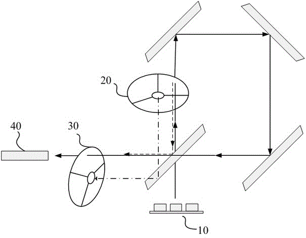
[0040] The present invention aims to provide a light source, such as image 3 As shown, it includes a laser 10, and the laser emitted by the laser 10 enters the fluorescent wheel 20. With the periodic rotation of the fluorescent wheel, the fluorescent wheel 20 receives part of the laser light and generates fluorescence and transmits part of the laser. After combining the light at 40, it enters the color filter wheel 30. After being filtered and transmitted by the filter color wheel 30, the three primary color lights are sequentially output, and finally enter the light rod 50 for homogenization to provide illumination for the optical-mechanical part.

[0041] Specifically, there can be one group of lasers 10, or multiple groups, such as two groups arranged vertically, and one beam is synthesized and emitted by a beam combining lens. In this embodiment, the laser 10 emits blue laser light.

[0042] Due to the large area of ​​the beam emitted by the laser, it needs to be shaped i...

Embodiment 2

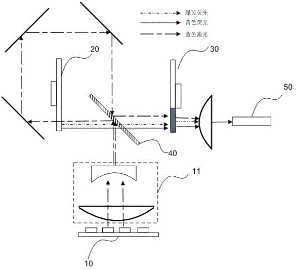
[0058] Embodiment 2 of the present invention proposes a light source, such as Figure 6 As shown, in the present embodiment, the laser emits laser light of two colors, respectively, the blue laser 11 emits blue laser, and the red laser 12 emits red laser. beam, the light-combining component 40 may be a dichroic sheet capable of transmitting blue laser light and reflecting red laser light.

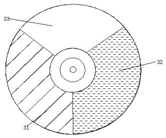
[0059] Both the combined blue laser light and the red laser light are incident on the fluorescent wheel 20. Correspondingly, the fluorescent wheel 20 includes a fluorescent area and a transmission area (not shown in the figure), wherein the fluorescent area includes green phosphor powder. The wavelength is shorter, and the blue laser is used as the laser excitation light to excite the green phosphor to emit green fluorescence. The transmission area of ​​the fluorescent wheel 20 specifically includes a blue laser transmission area and a red laser transmission area. According to the timing ...

Embodiment 3

[0068] Embodiment 3 of the present invention proposes a light source, such as Figure 8 As shown, the difference from Embodiment 2 is that in the light source provided by Embodiment 3 of the present invention, the red laser light emitted by the red laser 12 no longer shoots to the fluorescent wheel 20, but is arranged parallel to the optical path of the blue laser light emitted by the blue laser 11. Correspondingly, in the third embodiment of the present invention, the fluorescent wheel 20 only needs to be provided with a blue laser transmission area, and the blue laser light and the green fluorescent light are sequentially emitted from the back side of the fluorescent wheel 20, and reach the light-combining component 40 . The red laser light is also incident on the light-combining component 40 after being focused, and the three-color light is incident on the color filter wheel 30 after being combined. In the third embodiment of the present invention, the setting of the color f...


PUM


Abstract

The invention discloses a light source. The light source comprises a laser emitting laser beams in at least one color; a fluorescent wheel used for receiving laser irradiation and generating fluorescence in at least one color; and a color filter wheel which comprises a color filter area and a transmission area, wherein the color filter area is used for receiving, filtering and outputting the fluorescence in the at least one color, and the transmission area is used for transmitting the laser beams in the at least one color. Through arranging microstructures on the incident surface and the light-emitting surface of the transmission area, while the laser beams are transmitted, diffusion speckle dissipation can also be performed on the laser beams, functions of the color filter wheel part are diversified, application of individual speckle dissipation parts can also be omitted or reduced in light source configuration, and simplification of the light source configuration and compression of light source volume can be facilitated. The invention also provides a laser projection apparatus applying the light source provided by the technical scheme.

Description

technical field [0001] The invention relates to the technical field of projection display, in particular to a light source for projection display. Background technique [0002] As a solid-state light source, laser light source has a series of advantages such as high brightness, high efficiency, long life, good color gamut, and environmental protection, and has become the choice of emerging projection light source. [0003] Among the laser light sources currently used in the industry, wavelength conversion devices are used to generate fluorescence other than the laser color, and form three primary colors together with the laser. Such as figure 1 For example, the laser 10 emits laser light, specifically blue laser light, the wavelength conversion device 20 is coated with phosphor powder, specifically green phosphor powder and yellow phosphor powder, and the wavelength conversion device 20 rotates periodically, so that the laser spots hit the wavelength conversion device in tu...

Claims


Application Information

Patent Timeline
Patent Type & Authority Applications(China)
IPC IPC(8): G03B21/20
CPCG03B21/204G03B21/208
Inventor 田有良刘显荣王强李巍
Owner HISENSE
Why Eureka
Try Eureka