Control method of barn control system

A technology of control system and control method, applied in the direction of control/regulation system, non-electric variable control, and simultaneous control of multiple variables, etc., which can solve the problems of high energy consumption and low degree of automation

Inactive Publication Date: 2017-11-24
KAIFENG UNIV
View PDF5 Cites 0 Cited by
  • Summary
  • Abstract
  • Description
  • Claims
  • Application Information

AI Technical Summary

Problems solved by technology

However, the current air source heat pump barn still adopts the control method of ordinary dense barn, which fails to give full play to the energy efficiency of the air source heat pump, and has high energy consumption and low degree of automation

Method used


Image

  • Control method of barn control system
  • Control method of barn control system
  • Control method of barn control system

Examples


Embodiment 1

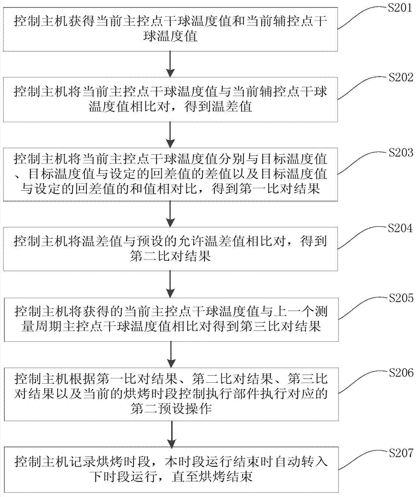
[0075] refer to figure 1 , an embodiment of the present invention provides a control method for a barn control system, the method is applied to an air source heat pump barn control system, and the air source heat pump barn control system includes a control host, a temperature sensor assembly, and an execution component. The temperature sensor assembly includes a main control point dry bulb temperature sensor and an auxiliary control point dry bulb temperature sensor, and the control host is connected with the main control point dry bulb temperature sensor, the auxiliary control point dry bulb temperature sensor and the executive The components are electrically connected.

[0076] The control method of the barn control system includes the following steps:

[0077] Step S101: The control host obtains the current dry-bulb temperature value of the main control point and the current dry-bulb temperature value of the auxiliary control point.

[0078] There are two dry bulb tempera...

Embodiment 2

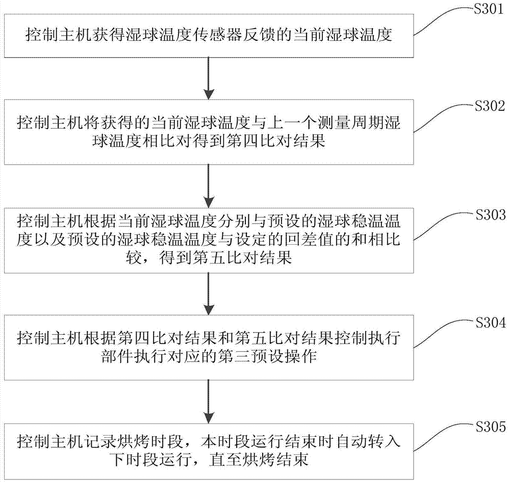
[0142] refer to image 3 , the present invention provides a control method of a barn control system, which is applied to the barn control system, the barn control system includes a control host, a temperature sensor assembly and an execution component, and the temperature sensor assembly includes a wet bulb temperature sensor , the control host is electrically connected to the temperature sensor assembly and the execution component respectively.

[0143] The control method of the barn control system includes the following steps:

[0144] Step S301: the control host obtains the current wet bulb temperature fed back by the wet bulb temperature sensor.

[0145] During the baking process controlled by the baking room control system, the wet bulb temperature sensor collects the temperature information in the drying room in real time to obtain the current wet bulb temperature, and feeds back the current wet bulb temperature to the control host, and sets the current wet bulb tempera...


PUM


Abstract

The invention provides a control method of a curing barn control system, and relates to the technical field of tobacco leaf curing. The control method of the barn control system is applied to the air source heat pump barn control system. The air source heat pump barn control system includes a control host, a temperature sensor assembly and an execution component. The execution part includes a circulating fan, a heat pump, and an automatic damper. The method includes: The control host obtains the dry and wet temperature fed back by the temperature sensor component, and controls the execution unit to perform corresponding operations according to the relationship between the obtained dry and wet temperature information and the target dry and wet temperature. The control method of the barn control system provided by the invention can make the change of the dry and wet temperature in the barn meet the requirements of the barn process, and realize the automatic control of the air source heat pump barn control system.

Description

technical field [0001] The invention relates to the technical field of tobacco leaf curing, in particular to a control method for a curing room control system. Background technique [0002] Tobacco leaf is an important part of my country's agricultural products. About 20 million farmers partly earn their income from tobacco leaf production every year, and the quality of tobacco leaf curing directly affects the production efficiency of tobacco leaves. Therefore, the quality of tobacco leaf curing is different from that of farmers of many kinds of tobacco leaves income is closely related. [0003] The curing barn is a special equipment for curing and processing tobacco leaves in the production of flue-cured tobacco. The barn control system that controls the curing progress is the most important part of the barn. The air source heat pump barn is a new energy barn that replaces coal-fired barns. The ideal equipment for the barn is also the inevitable requirement of environmental...

Claims


Application Information

Patent Timeline
Patent Type & Authority Patents(China)
IPC IPC(8): G05D27/02
CPCG05D27/02
Inventor 李世军杜诗超高明远边疆侯静秦亚萍
Owner KAIFENG UNIV
Why Eureka
Try Eureka