A multi-frequency antenna

A multi-frequency antenna and frequency band technology, which is applied to antennas, devices and electrical components that make the antennas work in different frequency bands at the same time, can solve the problems of inability to meet the bandwidth requirements of communication antennas, complex antenna layouts, and inability to achieve antennas. The effect of easy implementation, simple layout and diversified arrangement

Active Publication Date: 2018-06-26
PROSE TECH CO LTD
View PDF4 Cites 0 Cited by
  • Summary
  • Abstract
  • Description
  • Claims
  • Application Information

AI Technical Summary

Problems solved by technology

However, this method not only complicates the antenna layout, but the added radiator may also make the antenna unrealizable, and the isolation is poor
In addition, when the distance between two rows of radiators is very close, the horizontal wave width of each row of radiators diverges, and the low frequency F1 is too wide, for example, when the distance between two rows is 0.3-0.7 wavelengths, the low frequency wave width It may reach 75-110 degrees, which cannot meet the wave width requirements of communication antennas (usually the typical horizontal plane wave width requires 65 degrees)

Method used


Image

  • A multi-frequency antenna
  • A multi-frequency antenna
  • A multi-frequency antenna

Examples


Embodiment Construction

[0037] The present invention will be described in further detail below in conjunction with the accompanying drawings and specific embodiments, but not as a limitation of the present invention.

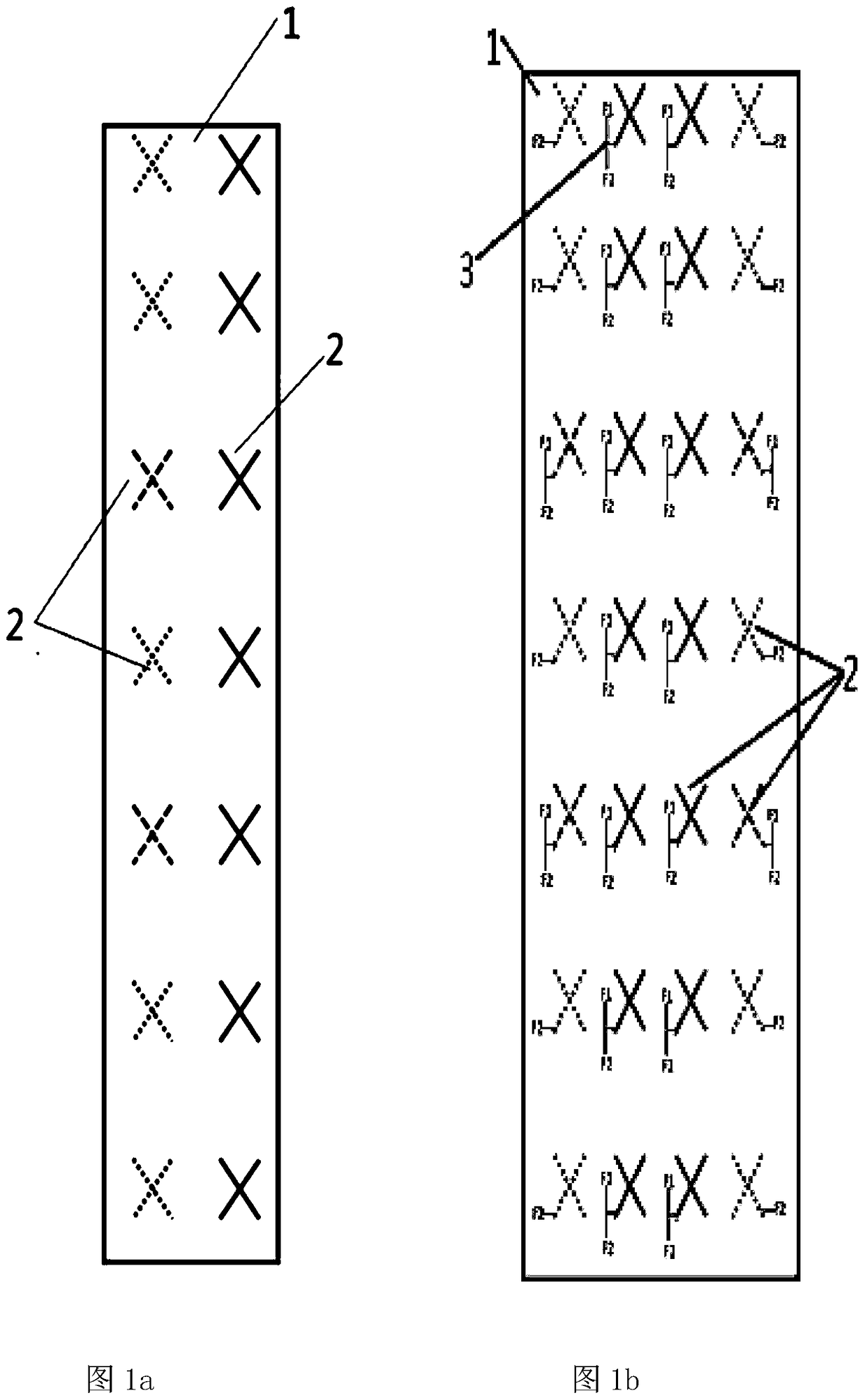
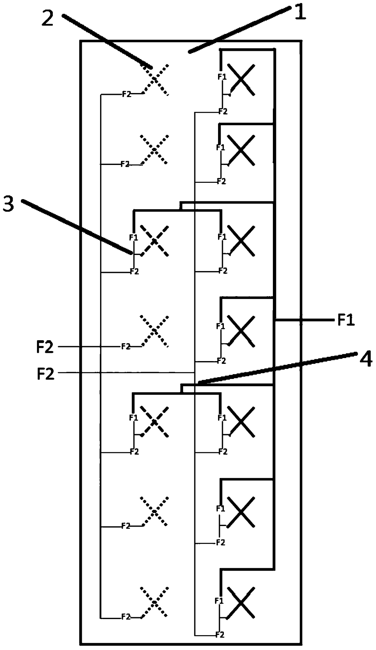
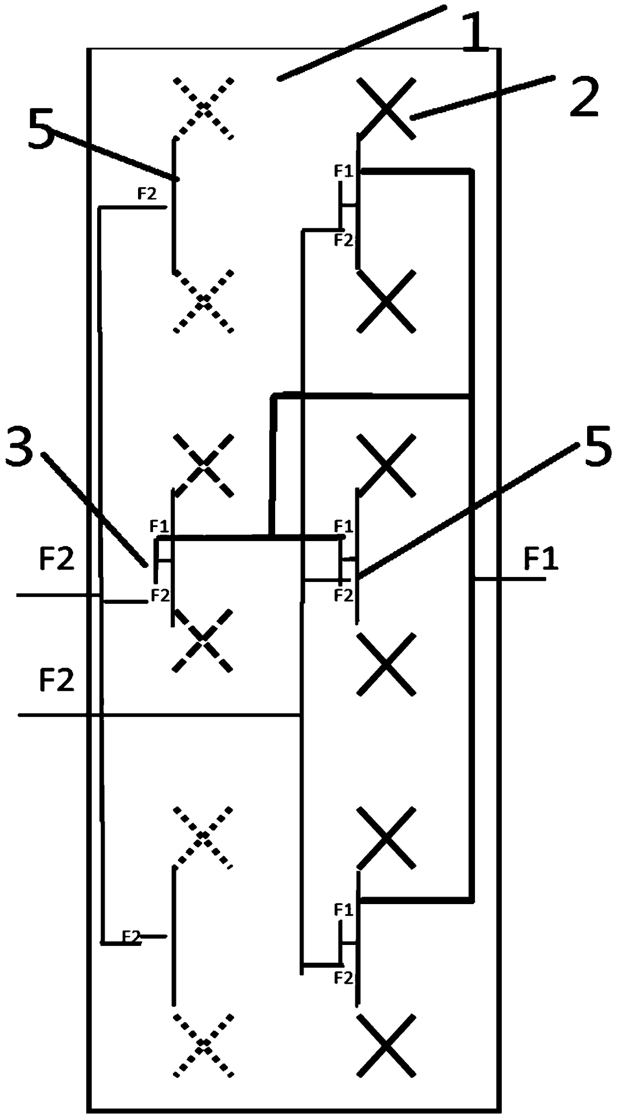
[0038] Such as figure 1 As shown, it is a structural diagram of a multi-frequency antenna 1 according to an embodiment of the present invention, wherein the multi-frequency antenna 1 of this embodiment includes at least one radiating element array group, such as figure 1 a shows a group, figure 1 b shows two groups; and each radiating element array group includes at least one first-type radiating element array and at least one second-type radiating element array adjacent to it, wherein each of the first-type radiating element arrays A radiating unit 2 can at least separate the F1 frequency band and the F2 frequency band, and some of the radiating units 2 in the second type of radiating unit array can at least separate the F1 frequency band and the F2 frequency band, and the F1 frequen...


PUM


Abstract

The present invention discloses a multi-frequency antenna, and is mainly applied to a field of wireless communications. The multi-frequency antenna comprises at least one set of radiating unit arrays, and each set of radiating unit arrays comprises at least one radiating unit array of a first type and at least one adjacent radiating unit array of a second type. Each radiating unit in the radiating unit array of the first type can at least separate frequency band F1 and frequency band F2, and a part of radiating units of the radiating unit array of the second type can at least separate frequency band F1 and frequency band F2. In each set of radiating unit arrays, a port for frequency band F1 of each radiating unit of the radiating unit array of the first type is connected to ports for frequency band F1 of the part of the radiating units of the radiating unit array of the second type via a power feeding network, and the power feeding network is connected to an output port for frequency band F1 of said set of the radiating unit array. The present invention has advantages of a simple layout and good isolation while satisfying a horizontal beamwidth standard for an output frequency band.

Description

technical field [0001] The invention relates to a multi-frequency antenna, which is mainly used in the field of wireless communication. Background technique [0002] With the continuous development of the wireless communication industry, the application of multi-frequency antennas is becoming more and more extensive; and the horizontal wave width of the frequency is one of the important factors affecting the multi-frequency antenna. Generally, the larger the horizontal wave width, the larger the coverage area of ​​the fan-shaped junction. The larger the antenna, the larger the propagation range, but once the tilt angle of the antenna is increased, beam distortion will easily occur, resulting in over-area coverage; and the smaller the horizontal wave width, the worse the coverage area at the sector junction. When the inclination angle of the antenna is adjusted, the coverage at the junction of the sectors can be improved in the degree of movement, and relatively speaking, it ...

Claims


Application Information

Patent Timeline
Patent Type & Authority Patents(China)
IPC IPC(8): H01Q5/20H01Q5/357
CPCH01Q5/20
Inventor 罗英涛
Owner PROSE TECH CO LTD
Why Eureka
Try Eureka