Valve arrangement

A valve device and solenoid valve technology, which is applied in the direction of valve device, valve operation/release device, transmission device control, etc., can solve the problem that the control of the brake cylinder can not be achieved in stages.

Active Publication Date: 2016-05-11
WABCO GMBH
View PDF7 Cites 4 Cited by
  • Summary
  • Abstract
  • Description
  • Claims
  • Application Information

AI Technical Summary

Problems solved by technology

However, this does not allow a graded actuation of the brake cylinders

Method used


Image

  • Valve arrangement
  • Valve arrangement
  • Valve arrangement

Examples


Embodiment Construction

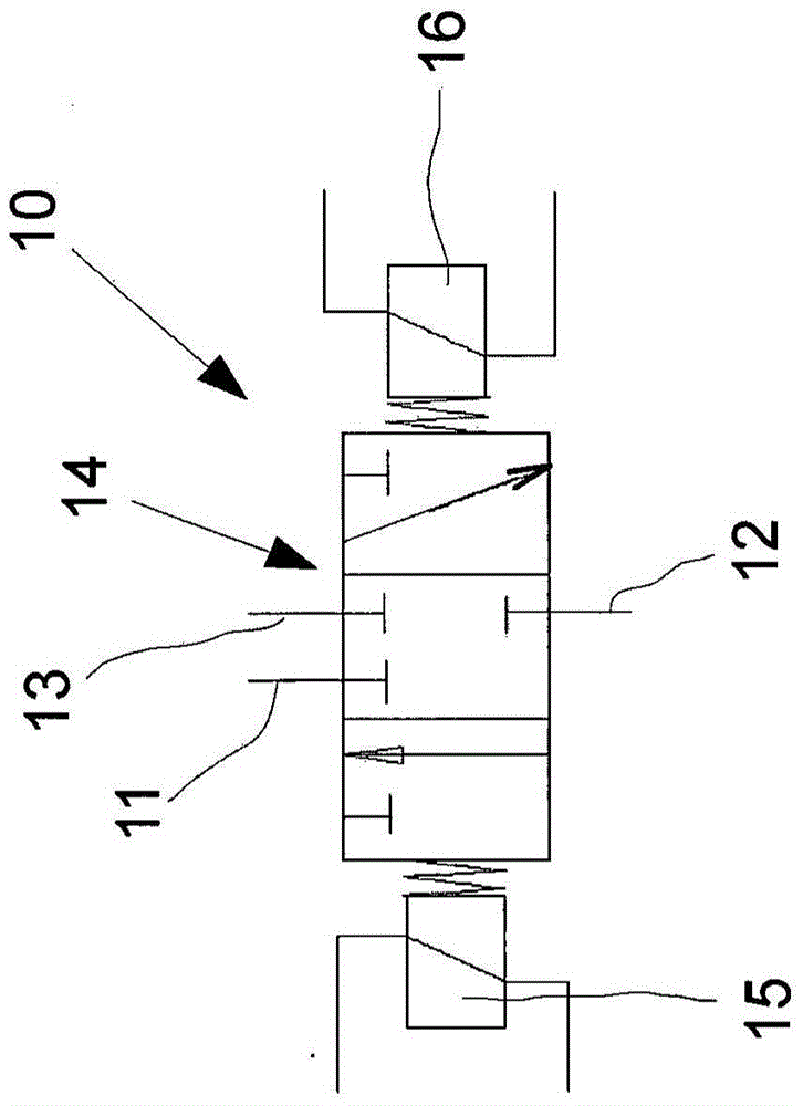
[0029] The solenoid valve 10 here has a compressed air connection 11 , a working connection 12 and a vent connection 13 . The solenoid valve 10 is designed as a 3 / 3-way directional control valve with an armature 14 and two coils 15 , 16 arranged coaxially and spaced apart from one another.

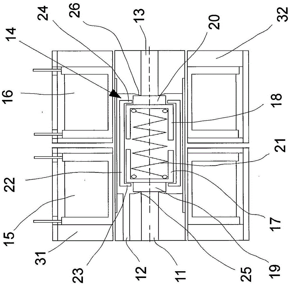
[0030] figure 2 A truncated intermediate position of the armature 14 is shown. At the ends, the armatures each have cylindrical covers 17 , 18 with sealing elements 19 , 20 . A compression spring 21 is arranged between the covers 17 , 18 , which presses the covers 17 , 18 away from each other. The force of the compression spring 21 is set so that the compressed air interface 11 and the air discharge interface 13 are closed when the solenoid valve 10 has no current.

[0031] The armature 14 has a cylindrical tubular piece 22 which accommodates the covers 17 , 18 inside and is provided with inwardly directed edges 23 , 24 on both ends thereof. The diameter of the covers 17 , 18 is set s...


PUM


Abstract

The invention relates to a valve arrangement for the admission of air to and venting of a fluid cylinder, in particular a spring-loaded fluid cylinder, preferably of transmission brake cylinders in pneumatically or hydraulically driven automated manual transmissions. According to the invention, a magnetic valve (10) is provided which has at least three connections (11, 12, 13) and three positions, and which further has a closed mid-position and NC function.

Description

technical field [0001] The invention relates to a valve arrangement according to the preamble of claim 1 . Furthermore, the invention relates to a transmission brake with a valve arrangement and to a transmission. Background technique [0002] Typically, shift transmissions are manually operated. For various reasons (comfort, less wear, etc.), an automated shift transmission can alternatively be installed in the vehicle. The shifting movement is implemented by the actuator. The actuator can be an integral part of a pneumatic or hydraulic system. Typically, commercial vehicles and buses are equipped with compressed air brakes. Pneumatic systems already present can accordingly be used for the actuation of automated shift transmissions. However, hydraulic actuation is also possible, especially in vehicles without pneumatic systems. [0003] A transmission brake can also be provided in automated shift transmissions. The actuation of the transmission brake takes place via ...

Claims


Application Information

Patent Timeline
Patent Type & Authority Applications(China)
IPC IPC(8): F16K11/20F16K31/06
CPCF16K11/207F16K31/0627F16K31/0679F16H61/0251F16H61/30F16K31/0606
Inventor 蒂莫·格拉赫斯特凡·克诺克汉斯约尔格·克拉夫特扬·施普赖贝格
Owner WABCO GMBH
Why Eureka
Try Eureka