Full-automatic puncture needle developing enhancing method based on encoder

A puncture needle and encoder technology, which is applied in the field of encoder-based fully automatic puncture needle development enhancement, can solve the problems of limited puncture range, inability to puncture, and inability to automatically identify puncture needles, etc. The effect of clear needle and enhanced echo signal

Inactive Publication Date: 2016-05-18
SHANTOU INST OF UITRASONIC INSTR CO LTD
View PDF7 Cites 8 Cited by
  • Summary
  • Abstract
  • Description
  • Claims
  • Application Information

AI Technical Summary

Problems solved by technology

[0006] In the above solution of JP9-28708A, the puncture angle of the puncture needle cannot be automatically identified, and multiple deflection angles need to be preset in the host, and before the operator uses the puncture needle to puncture, a deflection angle needs to be selected in advance on the host. Then the operator uses the puncture angle corresponding to the deflection angle to puncture
In this way, the image enhancement of the puncture needle cannot be fully automatic, and manual selection is required; more importantly, the actual puncture angle of the operator during puncture has a large deviation, that is, the puncture angle calculated by the preset deflection angle is different from the actual puncture angle. There is a large difference in the puncture angle, and there is also the problem that the reflected echo signal greatly deviates from the original direction, resulting in the weak echo signal received by the ultrasonic probe, which makes it difficult to form a clear image. Therefore, it is difficult to view on the monitor. The image of the puncture needle; in addition, the puncture angle of the operator is limited by the preset deflection angle, the puncture range is limited, and it is impossible to puncture at any angle, which brings considerable trouble to the actual operation

Method used


Image

  • Full-automatic puncture needle developing enhancing method based on encoder

Examples


Embodiment Construction

[0022] Further description will be given below in conjunction with the accompanying drawings and preferred embodiments of the present invention.

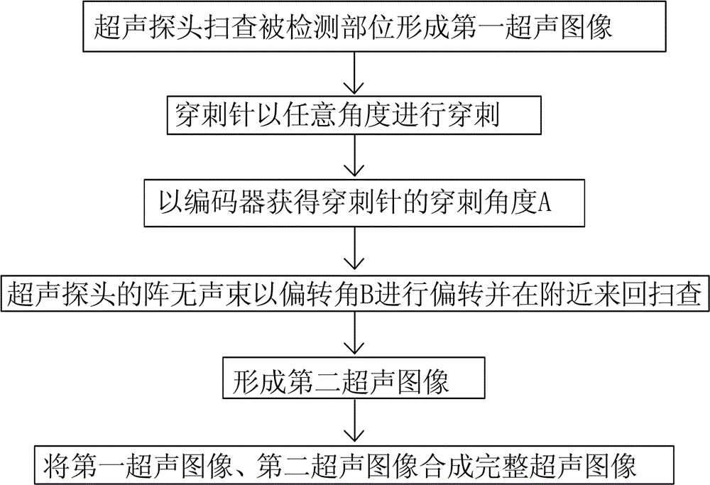
[0023] Such as figure 1 As shown, this encoder-based fully automatic puncture needle development enhancement method includes the following steps:

[0024] (1) The ultrasonic probe scans the detected part vertically to form the first ultrasonic image;

[0025] (2) The puncture needle punctures the detected part at any angle;

[0026] (3) Obtain the puncture angle of the puncture needle through the encoder installed between the ultrasonic probe and the puncture needle, and use the vertical direction as a reference to record the puncture angle as A, and at the same time record the puncture angle as A and upload it to the host;

[0027] The above-mentioned puncture needle is mounted on the ultrasonic probe through a puncture adapter, the puncture adapter includes a puncture frame and a puncture guide sleeve, the puncture frame is deta...


PUM


Abstract

A full-automatic puncture needle developing enhancing method based on an encoder includes the following steps that a detected portion is scanned through an ultrasonic probe in the vertical direction to form a first ultrasonic image; a puncture needle punctures the detected portion at any angle; the encoder installed between the ultrasonic probe and the puncture needle obtains a puncture angle A of the puncture needle; delay of an array element acoustic beam of the ultrasonic probe is controlled through a host, and the array element acoustic beam of the ultrasonic probe deviates by a deviation angle B and is used for scanning nearby back and forth; a second ultrasonic image based on the puncture needle is formed; the first ultrasonic image and the second ultrasonic image are synthesized into a complete ultrasonic image. The puncture needle is inserted at any angle, the puncture angle of the puncture needle is obtained through the encoder, the deviation angle B does not need to be preset, and developing enhancement of the puncture needle is achieved in a full-automatic mode. The deviation angle B of the array element acoustic beam is calculated through the puncture angle A, deviation does not exist, and the clearer second ultrasonic image is formed; puncture and scanning are easier and more convenient.

Description

technical field [0001] The invention relates to an image enhancement method, in particular to an encoder-based fully automatic puncture needle development enhancement method. Background technique [0002] Ultrasound diagnostic devices generally include a host, an ultrasound probe, a puncture needle, a puncture adapter, and an imaging system. The puncture needle is mounted on the ultrasound probe through the puncture adapter, so that a biopsy can be performed at a specific position of the detected site through the puncture needle. [0003] When performing scan imaging, the display of the ultrasonic diagnostic device displays the insertion guide of the puncture needle, and the operator can simultaneously confirm the image of the detected part and the movement of the puncture needle on the display, so as to perform safe puncture operations (such as biopsy, drainage, etc.). [0004] However, due to the insertion angle of the puncture needle, the array element sound beam emitted...

Claims


Application Information

Patent Timeline
Patent Type & Authority Applications(China)
IPC IPC(8): A61B8/00
CPCA61B8/5238
Inventor 李德来林国臻郭境峰蔡泽杭
Owner SHANTOU INST OF UITRASONIC INSTR CO LTD
Why Eureka
Try Eureka