Oil-water separation chamber of kitchen waste separation equipment

A technology for separation of kitchen waste and oil and water, which is applied in liquid separation, separation methods, grease/oily substance/floating matter removal devices, etc. Ineffective action, strict logic control, good oil quality

Active Publication Date: 2016-05-18
ANHUI TIANJIAN ENVIRONMENTAL PROTECTION
View PDF7 Cites 1 Cited by
  • Summary
  • Abstract
  • Description
  • Claims
  • Application Information

AI Technical Summary

Problems solved by technology

[0003] The current swill separation equipment (such as conventional oil separators) generally has two problems in the compartment separation and fluid direction: on the one hand, there is a dead zone in the liquid flow, that is, the liquid retained in some areas (or horizontal or vertical ranges) cannot be obtained. With flow replacement, the organic matter in the water will gradually rot and become smelly; on the other hand, the separated grease layer needs to be filled up to a certain amount before being discharged, and a large area of ​​grease scum exposed to the air for a lon...

Method used


Image

  • Oil-water separation chamber of kitchen waste separation equipment
  • Oil-water separation chamber of kitchen waste separation equipment
  • Oil-water separation chamber of kitchen waste separation equipment

Examples


Embodiment Construction

[0021] The following will clearly and completely describe the technical solutions in the embodiments of the present invention with reference to the accompanying drawings in the embodiments of the present invention. Obviously, the described embodiments are only some, not all, embodiments of the present invention. Based on the embodiments of the present invention, all other embodiments obtained by persons of ordinary skill in the art without making creative efforts belong to the protection scope of the present invention.

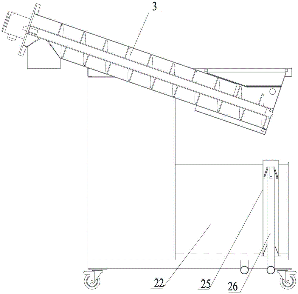
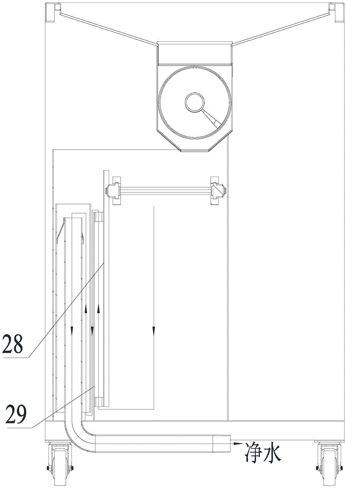
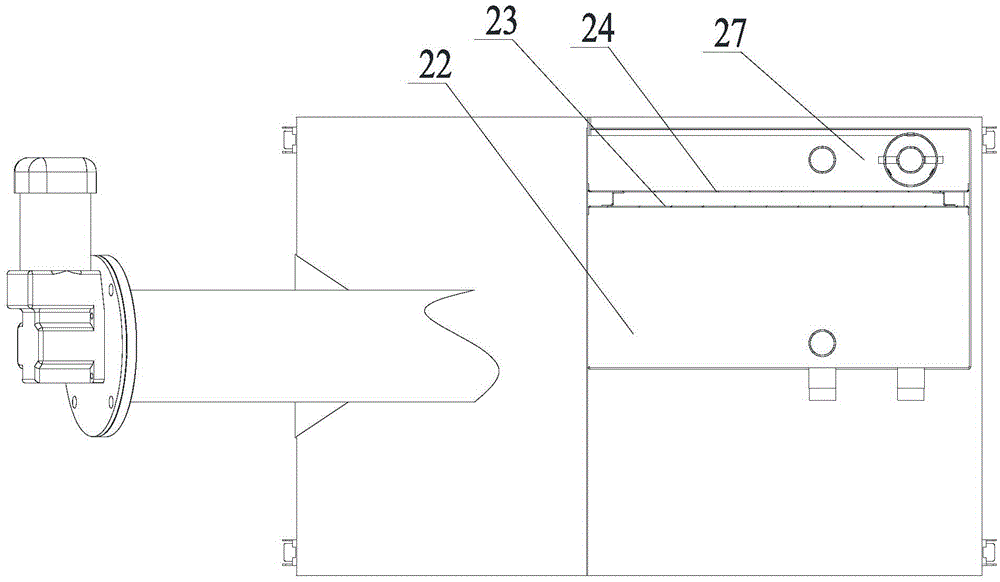
[0022] The kitchen waste separation device of the present invention includes a feeding system and an oil-water separation box. The feeding system separates the oil and water from the kitchen waste and outputs the oil and water to the oil-water separation box. The oil-water separation box is equipped with an oil storage room. The water-containing grease scraped by the oil scraper in the oil-water separation box is filtered by the oil storage tank and flows into...


PUM


Abstract

The invention discloses an oil-water separation chamber of kitchen waste separation equipment. The oil-water separation chamber is provided with a flow channel deodorizing system and an automatic oil drum filling system; the flow channel deodorizing system comprises a plurality of combined baffles; the interior of the oil-water separation chamber is segmented by the combined baffles, and each combined baffle is formed by a front plate and a back plate which are same in size and parallel to each other through dislocation at a certain distance in a spaced mode, wherein the upper surface of the front plate is higher than the lower surface of the back plate, a certain distance exists between the upper surface of the front plate and the bottom face of the oil-water separation chamber, the lower surface of the back plate is connected with the bottom face of the oil-water separation chamber, and a certain distance exists between the upper surface of the back plate and the top face of the oil-water separation chamber. In the automatic oil drum filling system, when the top elevation of a water layer reaches the H water high, a controller controls an electrically-controlled drainage ball valve to be switched on to start a drainage action, and when the top elevation of the water layer reaches the H water low, drainage is stopped; when the top elevation of an oil layer reaches the H oil high, the controller controls an electrically-controlled oil drainage ball valve to be switched on to start an oil drainage action, oil is filled in an oil storage drum, and when the top elevation of the oil layer reaches the H oil low, oil drainage is stopped.

Description

technical field [0001] The invention relates to an oil-water separation chamber, in particular to an oil-water separation chamber of kitchen waste separation equipment. Background technique [0002] At present, with the acceleration of urban development and urbanization, the problems of kitchen swill treatment and sewage discharge have become increasingly prominent. The discharge of kitchen swill is different from ordinary sewage discharge. First, oil-water separation is required, and sundries and sludge need to be removed. Sewage discharge also needs to meet the requirements of the "Water Quality Standards for Urban Sewage Discharge into Sewers". Otherwise, the drainage network and subsequent All sewage treatment stations will bring adverse impacts. [0003] The current swill separation equipment (such as conventional oil separators) generally has two problems in the compartment separation and fluid direction: on the one hand, there is a dead zone in the liquid flow, that ...

Claims


Application Information

Patent Timeline
IPC IPC(8): C02F1/40G05D9/12
CPCC02F1/40G05D9/12
Inventor 孟行健温舒平
Owner ANHUI TIANJIAN ENVIRONMENTAL PROTECTION
Why Eureka
Try Eureka