Oil-water separation chamber of kitchen waste separation equipment

A kitchen waste, oil-water separation technology, applied in the direction of liquid separation, separation method, grease/oily substance/floating matter removal device, etc., can solve the problems of unknown amount of oil, difficult self-flow, difficult separation of oil and water, etc., to achieve elimination Ineffective action, strict logic control, and good oil appearance

Active Publication Date: 2018-04-20
ANHUI TIANJIAN ENVIRONMENTAL PROTECTION
View PDF7 Cites 0 Cited by
  • Summary
  • Abstract
  • Description
  • Claims
  • Application Information

AI Technical Summary

Problems solved by technology

[0003] The current swill separation equipment (such as conventional oil separators) generally has two problems in the compartment separation and fluid direction: on the one hand, there is a dead zone in the liquid flow, that is, the liquid retained in some areas (or horizontal or vertical ranges) cannot be obtained. With flow replacement, the organic matter in the water will gradually rot and become smelly; on the other hand, the separated grease layer needs to be filled up to a certain amount before being discharged, and a large area of ​​grease scum exposed to the air for a long time will remain in the equipment compartment. will acidify and stink
[0004] Moreover, in the usual swill oil-water separation equipment, the separated grease produced by it may be scraped into the oil barrel through the oil scraper, and the water in the barrel cannot be easily removed because it contains moisture at the same time; discharge, but it is difficult to self-flow into standard containers due to the difference in overflow height
There are generally a series of difficulties such as unknown oil volume, difficult separation of oil and water, and difficult loading of containers.

Method used


Image

  • Oil-water separation chamber of kitchen waste separation equipment
  • Oil-water separation chamber of kitchen waste separation equipment
  • Oil-water separation chamber of kitchen waste separation equipment

Examples


Embodiment Construction

[0021] The technical solutions in the embodiments of the present invention will be clearly and completely described below in conjunction with the accompanying drawings in the embodiments of the present invention. Obviously, the described embodiments are only a part of the embodiments of the present invention, rather than all the embodiments. Based on the embodiments of the present invention, all other embodiments obtained by those of ordinary skill in the art without creative work shall fall within the protection scope of the present invention.

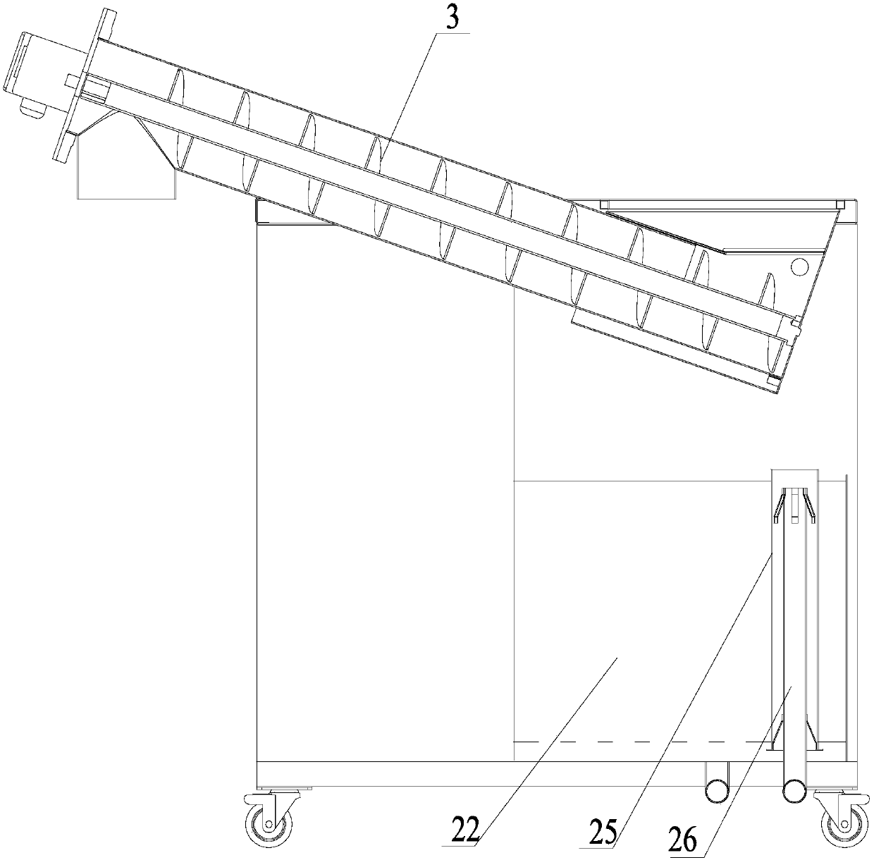
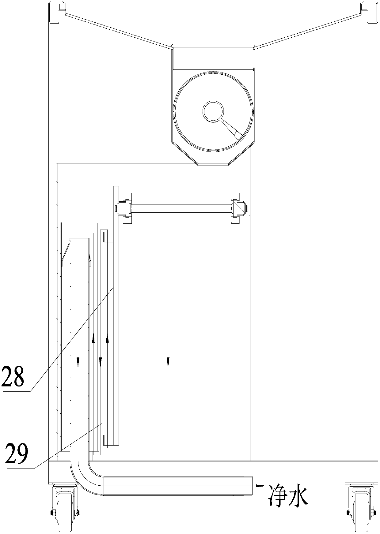
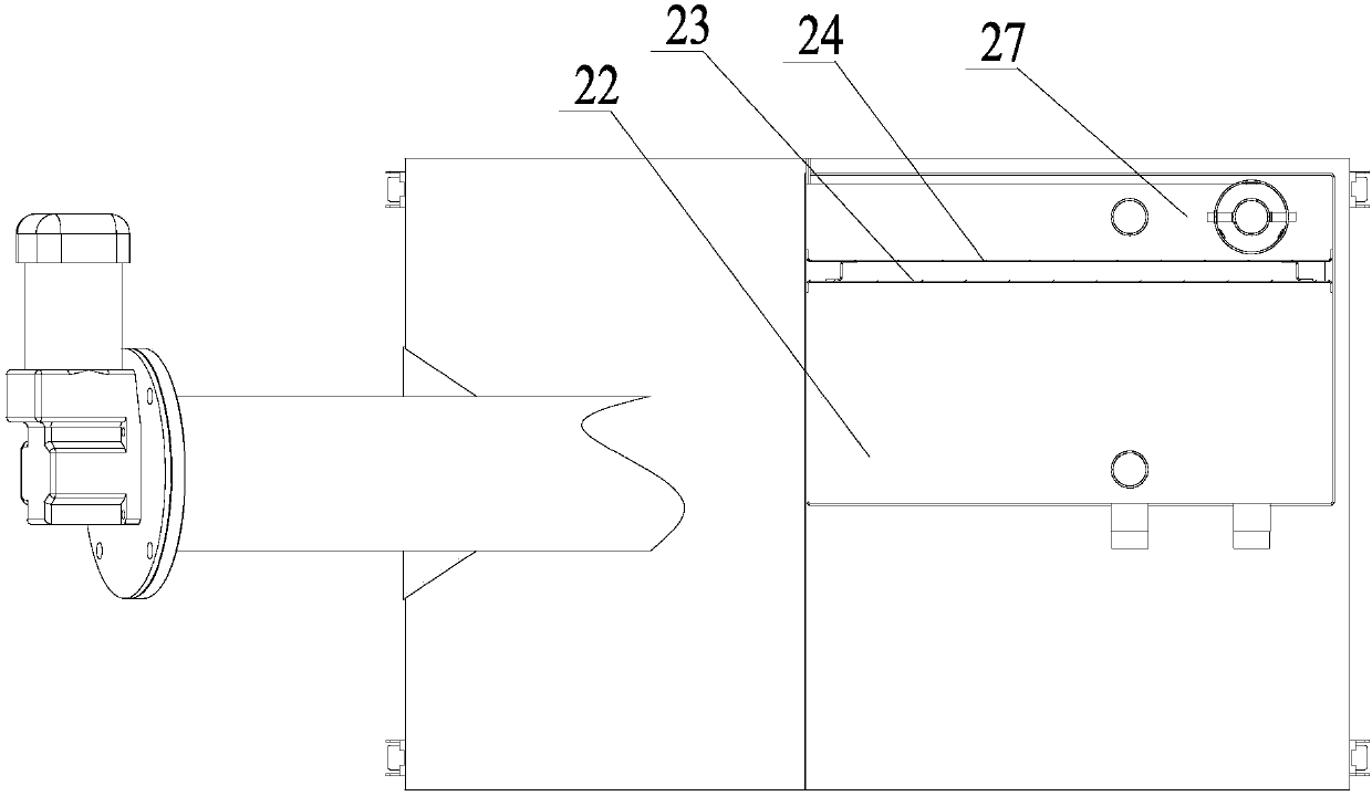
[0022] The food waste separation equipment of the present invention includes a feeding system and an oil-water separation tank. The feed system separates the kitchen waste from oil and water and outputs the oil and water to the oil and water separation tank, which is equipped with an oil storage chamber. The water-containing grease scraped by the oil-water separation tank through the oil scraper is filtered by the oil storage tank and fl...


PUM


Abstract

The invention discloses an oil-water separation chamber of kitchen waste separation equipment, which is provided with a flow channel deodorization system and an automatic oil barrel filling system. The runner anti-odor system includes several combined baffles. The oil-water separation chamber is divided by several combined baffles, and each combined baffle is composed of two parallel front plates and rear plates with the same size and a certain distance from each other. The front plate is higher than the bottom surface of the oil-water separation chamber at a certain distance from the bottom of the rear plate, and the bottom surface of the rear plate is connected with the bottom surface of the oil-water separation chamber and is at a certain distance from the top surface of the oil-water separation chamber. In the automatic filling system of oil drums, when the elevation of the top surface of the water layer reaches the height of water H, the controller controls to open the electric control drainage ball valve to start the water discharge action and stop when the elevation of the top surface of the water layer reaches the low level of H water; when the top surface of the oil layer When the elevation reaches the H oil height, the controller opens the electric control oil discharge ball valve to start the oil discharge action, fills into the oil storage barrel and stops when the elevation of the top surface of the oil layer reaches the H oil low.

Description

Technical field [0001] The invention relates to an oil-water separation chamber, in particular to an oil-water separation chamber of food waste separation equipment. Background technique [0002] At present, with the increasing acceleration of urban development and urbanization, the problems of kitchen swill treatment and sewage discharge have become increasingly prominent. Kitchen swill discharge is different from ordinary sewage discharge. First of all, oil-water separation is required, and debris and sludge need to be removed. Sewage discharge also needs to meet the requirements of the "Urban Sewage Discharge into Sewer Water Quality Standard", otherwise it will affect the drainage network and subsequent All sewage treatment stations will bring adverse effects. [0003] Existing swill separation equipment (such as conventional oil traps) generally have two problems in the compartment separation and fluid direction: on the one hand, there are dead zones in the liquid flow, that ...

Claims


Application Information

Patent Timeline
Patent Type & Authority Patents(China)
IPC IPC(8): C02F1/40G05D9/12
CPCC02F1/40G05D9/12
Inventor 孟行健温舒平
Owner ANHUI TIANJIAN ENVIRONMENTAL PROTECTION
Why Eureka
Try Eureka