Runner deodorization system of kitchen waste separation equipment and the separation equipment

A technology of kitchen waste and separation equipment, which is applied in the direction of liquid separation, separation method, grease/oily substance/floating matter removal device, etc., which can solve the problems of organic matter corruption and odor, acidification and odor, etc.

Inactive Publication Date: 2018-07-06
ANHUI TIANJIAN ENVIRONMENTAL PROTECTION
View PDF6 Cites 0 Cited by
  • Summary
  • Abstract
  • Description
  • Claims
  • Application Information

AI Technical Summary

Problems solved by technology

[0003] The current swill separation equipment (such as conventional oil separators) generally has two problems in the compartment separation and fluid direction: on the one hand, there is a dead zone in the liquid flow, that is, the liquid retained in some areas (or horizontal or vertical ranges) cannot be obtained. With flow replacement, the organic matter in the water will gradually rot and become smelly; on the other hand, the separated grease layer needs to be filled up to a certain amount before being discharged, and a large area of ​​grease scum exposed to the air for a long time will remain in the equipment compartment. will acidify and stink

Method used


Image

  • Runner deodorization system of kitchen waste separation equipment and the separation equipment
  • Runner deodorization system of kitchen waste separation equipment and the separation equipment
  • Runner deodorization system of kitchen waste separation equipment and the separation equipment

Examples


Embodiment Construction

[0018] The following will clearly and completely describe the technical solutions in the embodiments of the present invention with reference to the accompanying drawings in the embodiments of the present invention. Obviously, the described embodiments are only some, not all, embodiments of the present invention. Based on the embodiments of the present invention, all other embodiments obtained by persons of ordinary skill in the art without making creative efforts belong to the protection scope of the present invention.

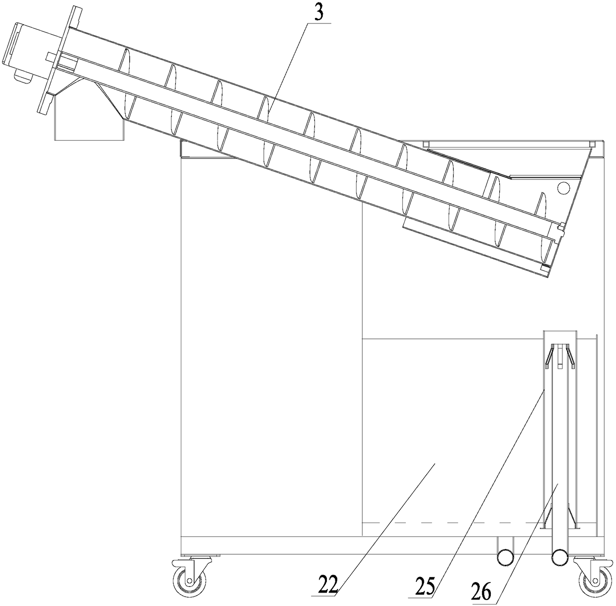
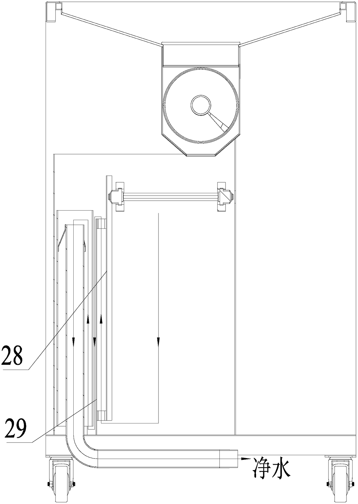
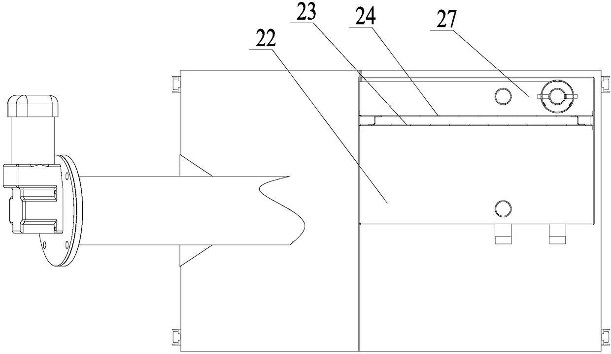
[0019] The invention is based on pipeline fluid mechanics and gravity separation technology, and is specifically applied to the design of separation chambers and separation liquid flow channels of swill separation equipment. Please also refer to figure 1 , figure 2 and image 3 , The kitchen waste separation device of the present invention includes an oil-water separation chamber 22 and a sundry separation box. After the debris separation box filters out t...


PUM


Abstract

The invention discloses a flow channel deodorization system of kitchen waste separation equipment and the separation equipment. The flow channel deodorization system is set in the oil-water separation chamber of the kitchen waste separation equipment, and includes several combined baffles. The oil-water separation chamber is divided by several combined baffles, and each combined baffle is composed of two parallel front plates and rear plates with the same size and a certain distance from each other. Between the front plate and the rear plate forms an inter-plate channel, the front plate is higher than the bottom of the oil-water separation chamber at a certain distance from the bottom of the oil-water separation chamber, and the bottom of the rear plate is connected with the bottom surface of the oil-water separation chamber at a certain distance from the top surface of the oil-water separation chamber. Under the action of the external fluid, the water climbs from bottom to top along the inter-plate channel of the first combined baffle and enters the upper part of the next oil-water separation chamber, and then enters the inter-plate channel of the next combined baffle, and advances sequentially, starting from the last combined baffle. The channel between the plates of the baffle climbs out of the oil-water separation chamber from bottom to top. The invention also discloses kitchen waste separation equipment with the flow channel deodorization system.

Description

technical field [0001] The invention relates to a flow channel deodorization system, in particular to a flow channel deodorization system of kitchen waste separation equipment and the kitchen waste separation equipment. Background technique [0002] At present, with the acceleration of urban development and urbanization, the problems of kitchen swill treatment and sewage discharge have become increasingly prominent. The discharge of kitchen swill is different from ordinary sewage discharge. First, oil-water separation is required, and sundries and sludge need to be removed. Sewage discharge also needs to meet the requirements of the "Water Quality Standards for Urban Sewage Discharge into Sewers". Otherwise, the drainage network and subsequent All sewage treatment stations will bring adverse impacts. [0003] The current swill separation equipment (such as conventional oil separators) generally has two problems in the compartment separation and fluid direction: on the one h...

Claims


Application Information

Patent Timeline
Patent Type & Authority Patents(China)
IPC IPC(8): C02F1/40
CPCC02F1/40
Inventor 孟行健温舒平
Owner ANHUI TIANJIAN ENVIRONMENTAL PROTECTION
Why Eureka
Try Eureka