
Spiral filtration dehydrator

A filtration dehydration and spiral technology, applied in filtration separation, moving filter element filter, dewatering/drying/concentrating sludge treatment, etc. Low requirements for incoming materials, convenient operation and maintenance, and low power consumption

Inactive Publication Date: 2017-01-18
SHANDONG CHENZHONG MACHINERY
View PDF7 Cites 8 Cited by
  • Summary
  • Abstract
  • Description
  • Claims
  • Application Information

AI Technical Summary

Problems solved by technology

The existing spiral filter dehydrator uses a large amount of flocculant, the dehydration effect is poor, and the requirements for incoming materials are high

Method used


Image

  • Spiral filtration dehydrator
  • Spiral filtration dehydrator
  • Spiral filtration dehydrator

Examples


Embodiment Construction

[0025] The present invention will be further described below in conjunction with accompanying drawing:

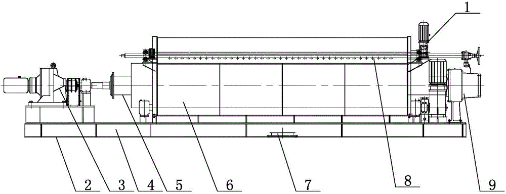
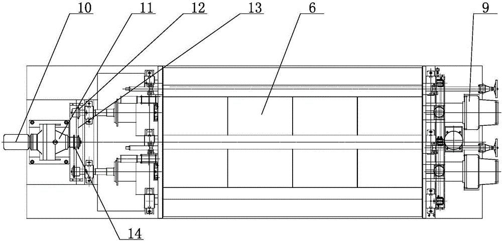
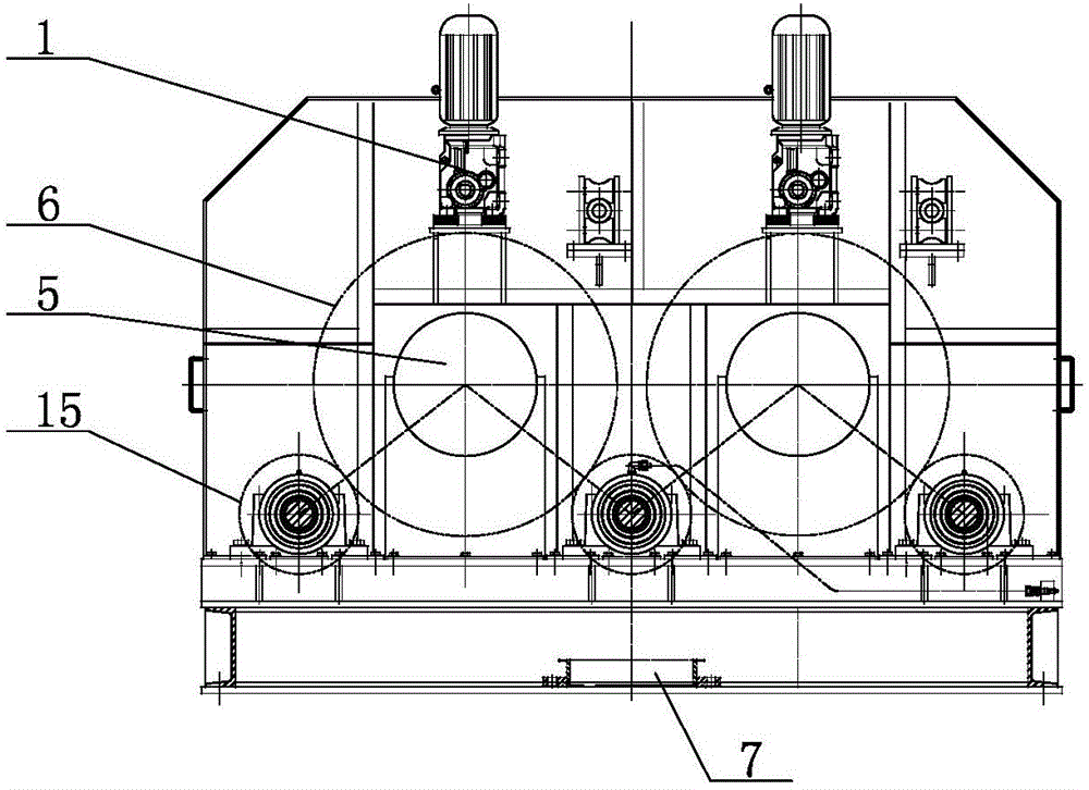
[0026] Such as Figure 1 to Figure 4 As shown, the spiral filter dehydrator of the present invention includes a frame 2, two screw shafts 5 are arranged side by side on the frame 2, one end of the screw shaft 5 is connected to the main shaft transmission device 3, and the two screw shafts 5 are installed on the two filter cartridges respectively. 6, a tugboat shaft 15 is set between the outer walls of the two filter cartridges 6 and between the filter cartridges 6, and one end of the tugboat shaft 15 is connected to the driving device, and the two ends of the filter cartridge 6 are respectively the feed inlet 9 and the discharge outlet, and the frame 2 Corresponding to the discharge port, the feeding port 4 is respectively set, the filtrate outlet 7 is respectively set at the middle position corresponding to the filter cartridge 6 on the frame 2, and the brush roller device...


PUM

PropertyMeasurementUnit
diameteraaaaaaaaaa
diameteraaaaaaaaaa

Abstract

The invention is widely applicable to the technical field of dehydration of paper mill sludge, electroplating sludge, leather sludge, domestic sludge and various types of sludge and particularly relates to a spiral filtration dehydrator. The spiral filtration dehydrator comprises a rack, wherein two spiral shafts are arranged on the rack in parallel, one end of each spiral shaft is connected with a spindle driving device, the two spiral shafts are respectively installed in two filter cartridges, towing wheel shafts are arranged between the outer side walls of the two filter cartridges and the two filter cartridges, one end of each towing wheel shaft is connected with a driving device, two ends of each filter cartridge are respectively a feeding port and a discharging port, the rack is provided with blanking port corresponding to the discharging ports, filtrate outlets are respectively formed in the middle positions, corresponding to the filter cartridges, on the rack, bristle brush roller devices are respectively arranged above the two filter cartridges, and a flushing water device is arranged on one side of the bristle brush roller devices. The spiral filtration dehydrator can decrease flocculant usage amount, adjust spiral and the roller rotation speed according to feeding concentration and control the staying and dehydration time of the sludge in a device. A dehydration effect is good, and material requirements are low. The outlet sludge concentration is adjustable, automatic operation is achieved, and labor intensity is low.

Description

technical field [0001] The invention relates to a spiral filter dehydrator, which is widely applicable to various types of sludge pre-dehydration technologies such as papermaking sludge, chemical sludge, printing and dyeing sludge, heavy oil sludge, electroplating sludge, leather sludge, and domestic sludge. field. Background technique [0002] The spiral filter dehydrator uses a porous filter medium sieve drum to intercept the solid particles in the mixture of liquid and solid particles, so as to achieve the purpose of solid-liquid separation. It can remove a large amount of free water from low-concentration sludge, further increase the sludge concentration, and reduce the dehydration pressure of the subsequent dehydration section. The existing spiral filter dehydrator uses a large amount of flocculant, the dehydration effect is poor, and the requirements for incoming materials are high. Contents of the invention [0003] The technical problem to be solved by the presen...

Claims


Application Information

Patent Timeline
Patent Type & Authority Applications(China)
IPC IPC(8): B01D33/37B01D33/11B01D33/46B01D33/48C02F11/12
CPCB01D33/11B01D33/37B01D33/461B01D33/48C02F11/125
Inventor 崔利胜张楷荆强刘卫平赵向河郭虎
Owner SHANDONG CHENZHONG MACHINERY
Learn More