A rotary pyrolysis furnace

A technology of rotating pyrolysis and pyrolysis furnaces, which is applied in the field of pyrolysis furnaces. It can solve the problems of reduced thermal insulation performance of the furnace body, inconvenient loading and unloading, and high cost of use, so as to reduce the work process, facilitate adjustment, and improve work efficiency. Effect

Active Publication Date: 2018-04-17
ZHEJIANG SHANGDING IND FURNACE
View PDF4 Cites 0 Cited by
  • Summary
  • Abstract
  • Description
  • Claims
  • Application Information

AI Technical Summary

Problems solved by technology

[0004] (1) The spring of the compression mechanism is inconvenient to assemble and disassemble due to its large expansion and contraction size, and it is prone to fatigue as the number of uses increases, resulting in uneven pressure on the pressing block, which in turn leads to poor sealing performance
[0005] (2) During the use of the second sealing strip, it will be worn, and the gas will easily leak out from the worn port
[0006] (3) The pressing mechanism cannot directly provide space for installing thermal insulation cotton, resulting in a decrease in the thermal insulation performance of the furnace body
[0007] (4) During use, the first sealing strip is bound to be worn, and the sealing strip often needs to be replaced, and the use cost is high
[0008] The above sealing mechanism for preventing gas exchange is applied to the rotary pyrolysis furnace, so that during the use of the pyrolysis furnace, the gas diffuses from the inside of the furnace to the outside of the furnace, because the pyrolysis gas in the pyrolysis furnace becomes more complex and the composition Instable, resulting in unreliable operation of the pyrolysis furnace and low safety factor

Method used


Image

  • A rotary pyrolysis furnace
  • A rotary pyrolysis furnace
  • A rotary pyrolysis furnace

Examples


Embodiment 1

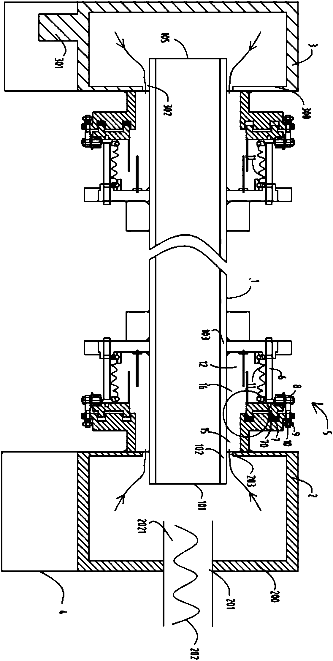
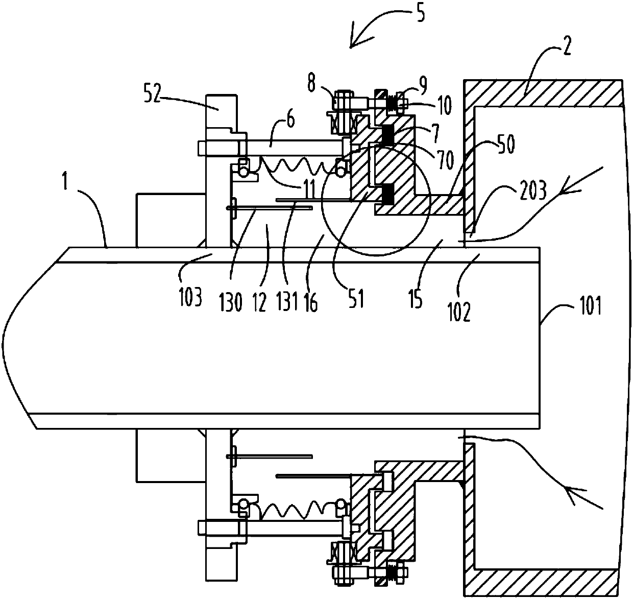
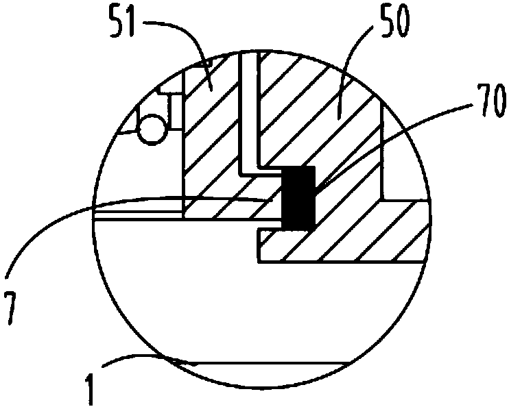
[0038] figure 1 It is a schematic diagram of the overall structure of Embodiment 1 of a rotary pyrolysis furnace; figure 2 It is a schematic structural view of the feed bin part in the rotary pyrolysis furnace according to Embodiment 1; image 3 It is a schematic diagram of the structure of the joint in the sealing mechanism for preventing gas exchange according to Embodiment 1; Figure 4 It is a schematic diagram of the structure of the gas flow channel opening in the sealing mechanism for preventing gas exchange according to Embodiment 1; Figure 5 It is a schematic diagram of the structure of the guide wheel device defined in the sealing mechanism for preventing gas exchange according to the first embodiment; Figure 6 It is a structural schematic diagram of the briquetting block in the sealing mechanism for preventing gas exchange according to the first embodiment; Figure 7 It is a schematic structural diagram of the receiving block in the sealing mechanism for preven...


PUM


Abstract

The invention relates to a rotary pyrolysis furnace which comprises a pyrolysis furnace (1), a feeding cabin (2), a discharging cabin (3), a bracket (4) and a sealing mechanism (5). The rotary sealing mechanism (5) comprises a pressed block (50), a pressing block (51), a supporting piece (52) and a connection rod (6); the pressing block (51) is provided with a first protruding block (511) and a second protruding block (512), and the pressing block (51) is provided with a pressing block lower end face (513); the pressed block (50) is provided with a first groove (501) and a second groove (502), the first protruding block (511) and the second protruding block (512) are connected with the first groove (501) and the second groove (502) in a closely matched mode to form a connection portion (7), and the pressed block (50) is provided with a pressed block lower end face (503); the pressing bock lower end face (513) is located above the pressed block lower end face (503). According to the pyrolysis carbonization furnace, the pressing block (51) and the pressed block (50) are connected through the protruding blocks and the grooves, a sealing function is achieved, and the sealing effect is better.

Description

technical field [0001] The invention relates to a pyrolysis furnace, in particular to a rotary pyrolysis furnace for preventing gas exchange through the gap formed between a fixed part and a rotating body part. Background technique [0002] The invention of the application number 201510072445.5 published on June 24, 2015 discloses a sealing mechanism for preventing gas exchange. The present invention is a sealing mechanism for preventing gas exchange. block, a pressing block that rotates in clearance with the rotating part, and a pressing mechanism that is fixedly connected with the rotating part. The pressing block exerts pressure on the receiving block through the pressing mechanism; the receiving block is provided with a first sealing strip; the cavity of the pressing block Place the second sealing strip; the second sealing strip realizes the sealing of the first gap formed between the pressing block and the outer wall of the rotating part; the screw of the pressing screw...

Claims


Application Information

Patent Timeline
Patent Type & Authority Patents(China)
IPC IPC(8): C10B1/10F16J15/16
CPCC10B1/10F16J15/16
Inventor 叶玉芳叶华健
Owner ZHEJIANG SHANGDING IND FURNACE
Why Eureka
Try Eureka