Device for hanging cable hooks

A cable hook and fixed jaw technology, which is applied to overhead lines/cable equipment, etc., can solve the problems of low work efficiency, inconvenient operation, and inability to expand and contract, and achieve the effect of improving work efficiency, simple device structure, and simple operation method.

Active Publication Date: 2016-05-18
中邮建技术有限公司
View PDF10 Cites 4 Cited by
  • Summary
  • Abstract
  • Description
  • Claims
  • Application Information

AI Technical Summary

Problems solved by technology

This auxiliary tool has the following disadvantages: 1. During the installation process, the cable hook is easy to drop, which is inconvenient to operate; 2. The operation method is complicated and the work efficiency is low; The jaws where the cable hooks are placed are at the same height, and the cable hooks on the steel strand cannot be removed on the ground; 4. It cannot be stretched and retracted, and it is inconvenient to carry; 5. The groove shape of the jaws is fixed, which cannot meet cables of different sizes. Hook Installation Requirements

Method used


Image

  • Device for hanging cable hooks
  • Device for hanging cable hooks
  • Device for hanging cable hooks

Examples


example 1

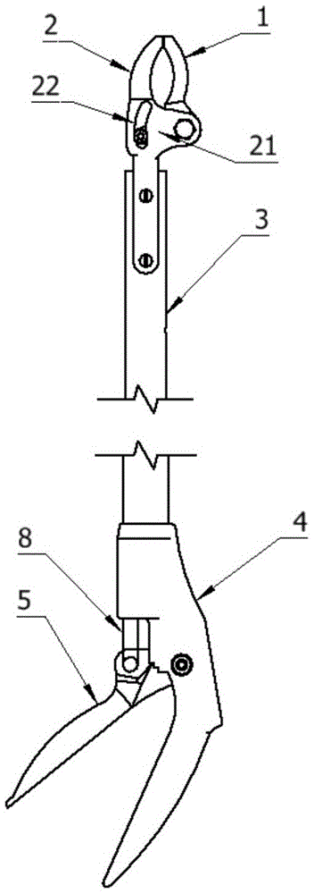
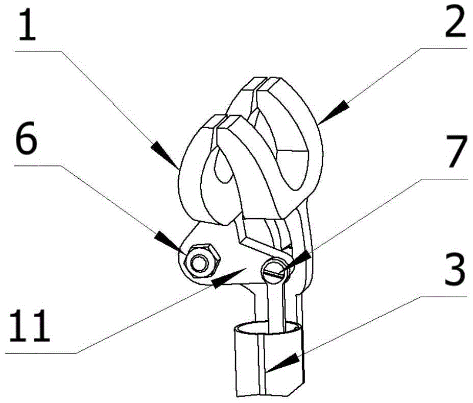
[0024] The structure of the device for hanging the cable hook is as follows figure 2 As shown, it includes a jaw part, a rod part and a handle part connected in sequence, the jaw part includes a fixed jaw 2 and a movable jaw 1, the rod part includes a telescopic rod 3 and a pull rod 8, and the handle part includes a fixed handle 4 and a movable handle 5. The top of telescopic rod 3 is provided with fixed jaw 2 and movable jaw 1, and the bottom is provided with fixed handle 4 and movable handle 5. The fixed jaw 2 and the movable jaw 1 are arc-shaped, which is convenient for clamping the cable hook. The structure of the jaw is as follows: image 3 shown. The lower end of the fixed jaw 2 is fixed on the upper end of the telescopic rod 3 by screw nuts. There is protrusion 21 in the middle part of the fixed jaw, and an L-shaped support 11 is arranged below the movable jaw. The other end is hingedly connected with the pull rod 8 in the telescoping rod 3 through the connecting s...

example 2

[0026] The structure of the device for hanging the cable hook is as follows Figure 6 As shown, it includes a jaw part, a rod part and a handle part connected in sequence, the jaw part includes a fixed jaw 2 and a movable jaw 1, the rod part includes a telescopic rod 3 and a pull rod 8, and the handle part includes a fixed handle 4 and a movable handle 5. The top of telescopic rod 3 is provided with fixed jaw 2 and movable jaw 1, and the bottom is provided with fixed handle 4 and movable handle 5. The heads of the fixed jaw 2 and the movable jaw 1 are equipped with V-shaped bayonets, which are convenient for clamping the steel bars at the cable hooks. The structure of the jaws is as follows: Figure 7 shown. The lower end of the fixed jaw 2 is fixed on the upper end of the telescopic rod 3 by screw nuts. There is a protrusion 21 in the middle of the fixed jaw 2, and an L-shaped bracket 11 is arranged below the movable jaw 1. The bending part of the L-shaped bracket 11 is hi...


PUM


Abstract

The invention discloses a device for hanging cable hooks. The device comprises a jaw part, a rod part and a handle part which are sequentially connected, the jaw part comprises a fixed jaw and a flexible jaw, the rod part comprises a telescopic rod and a pull rod, and the handle part comprises a fixed handle and a flexible handle. The fixed jaw is fixed at the upper end of the telescopic rod, a protrusion is arranged in the middle of the fixed jaw, the flexible jaw is hinged to the fixed jaw, the flexible jaw is hinged to the pull rod in the telescopic rod, the fixed handle is fixed at the lower end of the telescopic rod, the head of the flexible handle is hinged to the fixed handle, and a locking part is arranged on the flexible handle. According to the device for hanging the cable hooks, the cable hooks can be fixed at the upper end of the rod part, and the cable hooks with different sizes can be hanged on a steel strand; the cable hooks can be taken down only by loosening the fixed handle and the flexible handle; the length of the telescopic rod is adjustable, and the device is suitable for cable steel strands with different heights and convenient to carry; the size of the jaw is adjustable, and installation requirements of the cable hooks with different sizes can be met.

Description

technical field [0001] The invention relates to a device for hanging a cable hook, and belongs to the technical field of communication cable construction auxiliary tools. Background technique [0002] During the construction or use of the communication cable, it often slips from the high steel strand due to the unstable fixing of the cable hook. At this time, the construction personnel on the ground need to use auxiliary tools to rehang the cable hook back to the steel strand. In order to restore the communication cable to its original state of use. [0003] Existing helper structures such as figure 1 As shown, the upper part is a jaw provided with a groove, and the lower end of the jaw is fixedly connected with a support rod. During use, construction workers on the ground first place the cable hook in the groove of the jaws, and then hold the lower end of the support bar with their hands to install the cable hook back to its original position. This auxiliary tool has the...

Claims


Application Information

Patent Timeline
Patent Type & Authority Applications(China)
IPC IPC(8): H02G1/02
CPCH02G1/02
Inventor 魏雷杨建方恒武涂东耀
Owner 中邮建技术有限公司
Why Eureka
Try Eureka