Medical transfer frame

A technology of transfer frame and frame, which is applied in the field of medical transfer frame, which can solve the problems of increasing the difficulty of treatment, labor-saving, and difficult to move, and achieve the effect of reducing the probability of secondary injury, reducing physical exertion, and ensuring stability

Active Publication Date: 2016-05-25
天长市佳诺医疗器械有限公司
View PDF8 Cites 28 Cited by
  • Summary
  • Abstract
  • Description
  • Claims
  • Application Information

AI Technical Summary

Problems solved by technology

There are two major defects in this method: 1) the physical strength requirements of the nursing staff are extremely high, and it is extremely labor-intensive. After the nursing staff has performed treatment or operation, the physical strength will inevitably decline, and a large amount of physical strength needs to be expended in the process of transferring the patient. Having a bed mover undoubtedly increases the difficulty of implementation for the nursing staff; 2) It is easy to cause secondary injury to the patient. Among the patients, many parts of the body are damaged and it is not easy to move. The existing bed mover is in use During the process, the lifting operation of the nurse is required, and the stability of the lifting is poor. Therefore, each lifting may cause secondary damage to the patient, increasing the pain of the patient and increasing the difficulty of treatment.
And in reality, due to the different heights of the beds, the operation difficulty of the nursing staff is increased during the transfer process, and the risk of secondary injury to the patient is also increased.

Method used


Image

  • Medical transfer frame
  • Medical transfer frame
  • Medical transfer frame

Examples


Embodiment 1

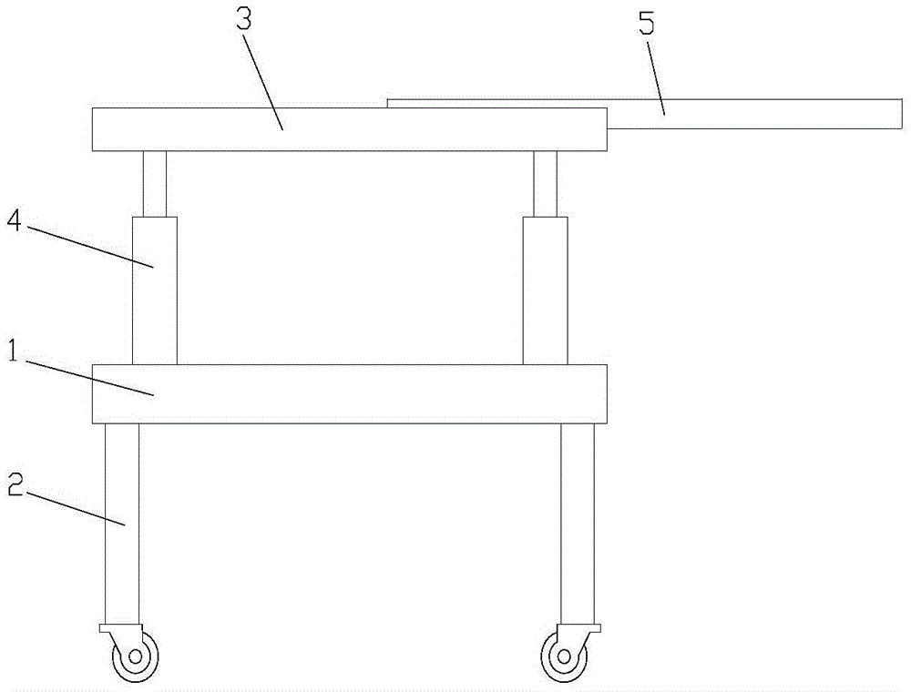
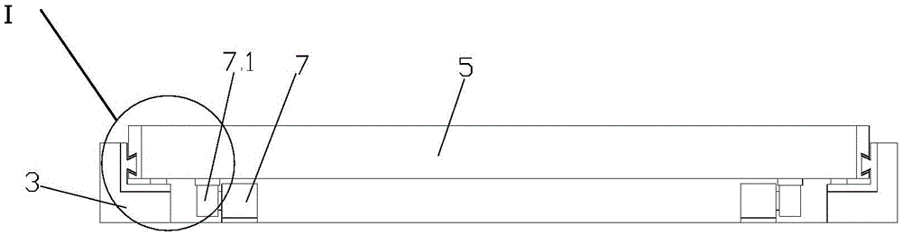
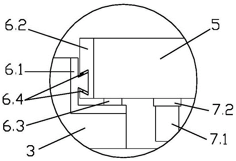
[0022] Embodiment 1: as figure 1 , figure 2 The medical transfer frame shown is a medical transfer frame, which includes a frame body 1, a support foot 2 at the bottom of the frame body 1, and a support frame 3 at the top of the frame body 1. The bottom of the support foot 2 is provided with universal wheels. The steering wheel has a self-locking function, which is convenient for moving the transfer frame and fixing the position of the transfer frame. The upper end of the frame body 1 is provided with a lifting mechanism for controlling the height and inclination angle of the support frame 3. The two ends of the frame body 1 in the length direction are front and rear. The two sides in the width direction of the frame body 1 are the left and right sides. The lifting mechanism is composed of four electric lifting columns 4. The four lifting columns 4 are distributed at the four corners of the top of the frame body 1. The bottom of the lifting column 4 is connected to The frame...


PUM


Abstract

The invention belongs to the technical field of medical appliances, and particularly relates to a medical transfer frame. The medical transfer frame comprises a frame body, supporting legs arranged at the bottom of the frame body and a support positioned at the top of the frame body, wherein a lifting mechanism is arranged at the upper end of the frame body; the top end of the lifting mechanism is connected with the support; a moving plate is arranged on the support, and can slide out toward left and right sides; the front and rear ends of the moving plate are in sliding connection with those of the support by virtue of a sliding mating part; the sliding mating part comprises an L-shaped fixed part and a sliding part; the outer side of the vertical part of the fixed part is connected with the support, and the inner side of the vertical part of the fixed part is in sliding fit with the sliding part; the sliding part is connected with the moving plate; the horizontal part of the fixed part extends to the bottom side of the moving plate, and is provided with a gliding part for supporting the moving plate. The medical transfer frame has a lifting function, can be retracted to left and right sides, is capable of facilitating patient transfer and greatly reducing pains of patients in the transferring process since the inclined angle can be adjusted, and is convenient to operate and labor-saving.

Description

technical field [0001] The invention belongs to the technical field of medical devices, and in particular relates to a medical transfer rack. Background technique [0002] Generally, in the course of clinical treatment and surgical treatment, the patient is often transferred from the hospital bed to the operating bed, or the bed is changed between the operating bed and the monitoring bed, which is often referred to as bed transfer in clinical practice. For patients who cannot move freely, moving the bed is especially critical. Most of the existing bed moving devices at this stage are single moving mattresses. Multiple nurses lift the patient from the original bed to the moving mattress, and then move the bed. The pad is carried to another bed by multiple caregivers. There are two major defects in this method: 1) the physical strength requirements of the nursing staff are extremely high, and it is extremely labor-intensive. After the nursing staff has performed treatment or ...

Claims


Application Information

Patent Timeline
Patent Type & Authority Applications(China)
IPC IPC(8): A61G7/14
CPCA61G7/1019A61G7/103A61G7/1046A61G7/1057A61G7/1073A61G2203/10
Inventor 吕欢
Owner 天长市佳诺医疗器械有限公司
Why Eureka
Try Eureka