Control method of rail milling operation

A control method and milling technology, applied in milling machine equipment, manufacturing tools, details of milling machine equipment, etc., can solve the problems of high energy consumption, large environmental pollution, and high construction cost, and achieve the effect of protecting the environment, reducing dust effects, and improving milling accuracy.

Active Publication Date: 2018-06-22
BEIJING TUOBOER TRACK MAINTENANCE TECH CO LTD
View PDF7 Cites 0 Cited by
  • Summary
  • Abstract
  • Description
  • Claims
  • Application Information

AI Technical Summary

Problems solved by technology

Third, the grinding process will cause a lot of smoke and dust, which will pollute the environment more
Fourth, the grinding process relies on friction to work, and the processing needs to consume more energy
In addition, the grinding vehicle is more than 110 meters long, and the cost is relatively high

Method used


Image

  • Control method of rail milling operation
  • Control method of rail milling operation
  • Control method of rail milling operation

Examples


Embodiment Construction

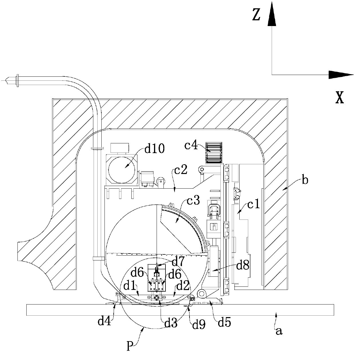
[0042] In order to illustrate the present invention more clearly, the following definitions are made: the direction along the length of the rail is defined as the X direction, the direction perpendicular to the side surface of the rail is defined as the Y direction, and the direction perpendicular to the upper surface of the rail is defined as the Z direction.

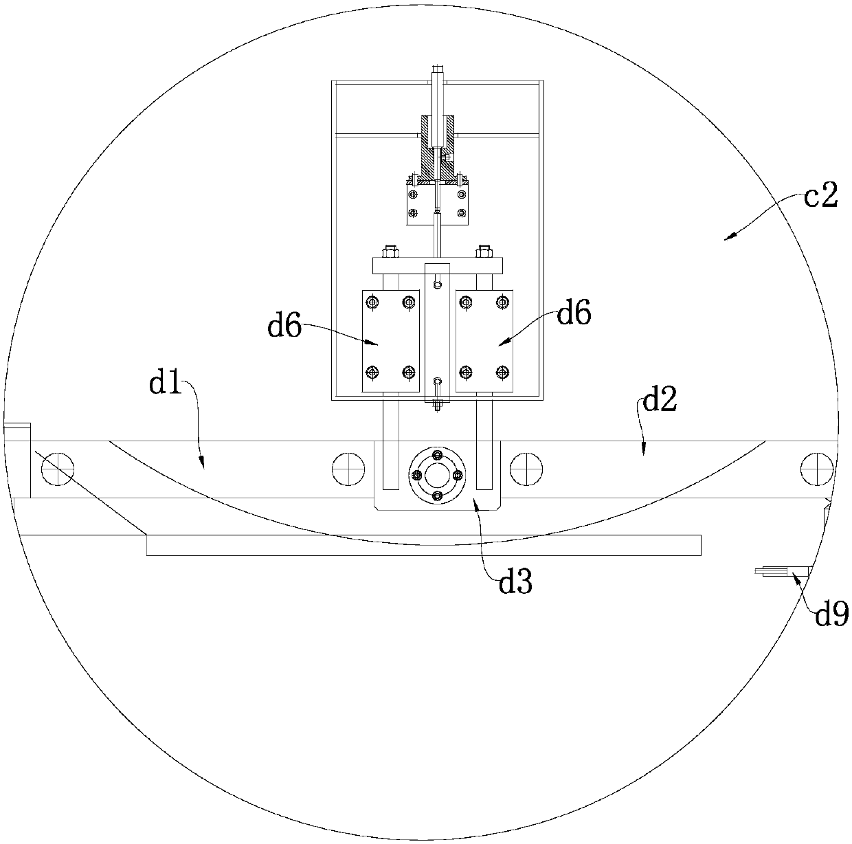
[0043] For the implementation of the present invention, a design such as Figure 1-2 The rail milling operation system shown; specifically, the rail milling operation system includes: a car body b, a milling execution unit and an auxiliary positioning unit.

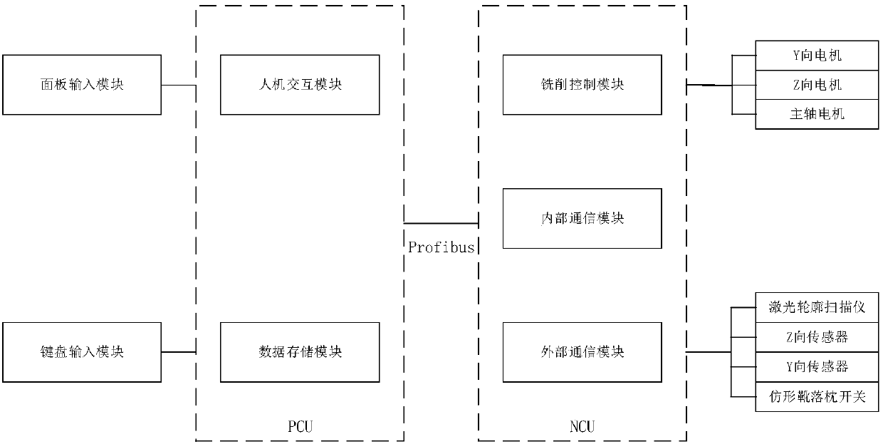
[0044] The milling execution unit includes: a cross slide c1, a cutter head frame c2, a cutter head c3, a Y-direction motor (not shown in the figure), a Z-direction motor c4 and a spindle motor (not shown in the figure);

[0045] The fixed end of the cross slide c1 is fixedly arranged on the car body b, and the movable end is fixedly connected with the cutter head...


PUM


Abstract

The invention provides a control method of a steel rail milling work and relates to a method for repairing a steel rail, aiming at providing the control method of the steel rail milling work, which has high milling precision and high milling efficiency, little pollution and low energy consumption. The control method comprises the following steps: S1: acquiring steel rail outline parameters; S2: carrying out tool setting; S3: initializing an auxiliary positioning device; and S4: carrying out the milling work, and starting a main shaft motor and a vehicle body. Under the driving of the vehicle body, a steel rail milling system moves at a constant speed along the direction of the steel rail, a right contact piece and a left contact piece are controlled to be in contact with the upper surface of the steel rail, and a lateral contact piece is controlled to be in contact with the lateral surface of the steel rail; a Z-directional sensor is used for measuring the height of a cutter disc in the Z direction in real time; a Y-directional sensor is used for measuring the distance between a finger tip of the lateral contact piece and the cutter disc in the Y direction in real time, so that a road condition is judged in real time; and furthermore, the cutter disc is continuously adjusted by a milling executing unit according to the road condition, and thus milling repairing of the steel rail is realized.

Description

technical field [0001] The invention relates to a rail repair method, in particular to a method for rail repair by means of milling. Background technique [0002] Aiming at the problem of rail maintenance in the field of rail transit, the existing technology is grinding type track maintenance. The principle is to fit the cross-sectional shape of the rail by enveloping the plane of multiple grinding wheels. When the train is running during work, each grinding wheel fits on the Rail surface, so as to realize the grinding of the rail surface. [0003] The disadvantages of rail grinding are poor precision, low efficiency, heavy pollution, high energy consumption, and high cost. First, the grinding process involves multiple grinding wheels enveloping and fitting the rail section, and the machining accuracy is relatively poor. Its two, the grinding amount of grinding processing is about 0.1 to 0.3 mm, and the operation efficiency is low. Its three, grinding processing can cause...

Claims


Application Information

Patent Timeline
Patent Type & Authority Patents(China)
IPC IPC(8): B23C3/00B23P6/00B23Q5/22
CPCB23C3/005B23P6/00B23Q5/22
Inventor 刘博
Owner BEIJING TUOBOER TRACK MAINTENANCE TECH CO LTD
Why Eureka
Try Eureka